
Basic machining operations Part 2
12. Basic machining operations Part 1
Screw threads
Threading consists of cutting a spiral ridge of even thickness around the surface of cylinders or cylindrical holes. There are two kinds of threads: external (outside threads on a cylinder) and internal (inside threads in a hole).
Screw threads are found on practically all machine structures.
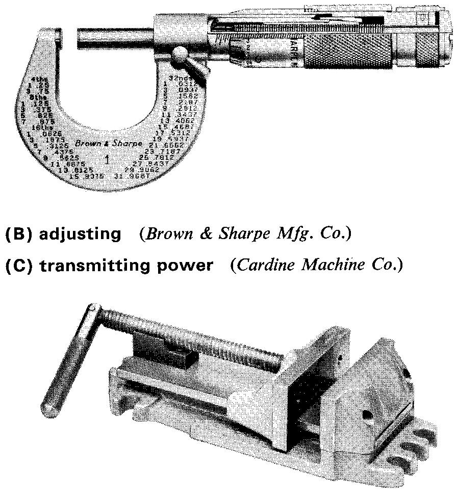
In general they are used for three main purposes as shown in Fig. 12-26: for holding parts together; for adjusting parts; and for transmitting power.
Fig. 12-26. Three main uses of screw threads


The machine draftsman and designer must know the specific purpose and demands of a screw thread before selecting an appropriate thread.
Screw thread terms
Because screw threads occur so often on machine parts, it is necessary for draftsmen to learn the thread terms commonly in use. Draftsmen should also know the various kinds of thread forms and how to draw and specify them.
Figure 12-27 illustrates common thread terms for external and internal threads. As we use these terms in the discussions of threads in the following pages, it might be well to refer back to this figure from time to time.
Fig. 12-27. Screw thread terms
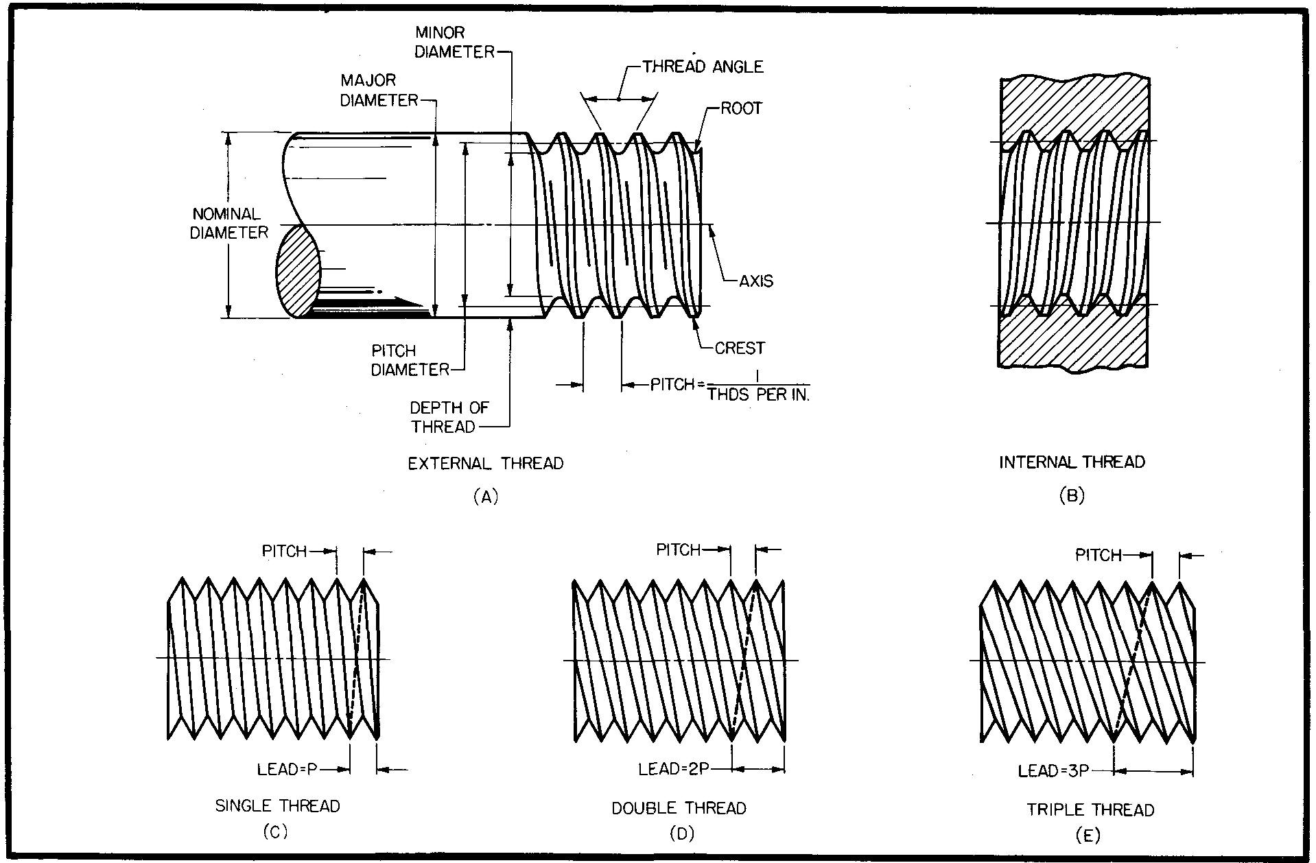
RIGHT HAND THREAD - a thread which winds by turning clockwise when advancing into its mating part. Threads are always assumed to be right hand unless otherwise specified. Figures C, D, and E are examples of right hand threads.
MULTIPLE THREADS - D and £ are examples, fig. 12-27. screw thread terms
LEFT HAND THREAD - a thread which winds by turning counterclockwise when advancing into its mating part. (See Fig. 12-39.)
LEAD — the distance a threaded part advances in a direction parallel to its center line (or axis) through one complete revolution.
Screw thread forms and their uses
Screw threads vary considerably in size and shape. Each thread form has been designed for special requirements. The term thread form means the shape of the profile, or cross section, of the thread.
Figure 12-28 shows nine common thread forms.
Fig. 12-28. Nine common thread forms
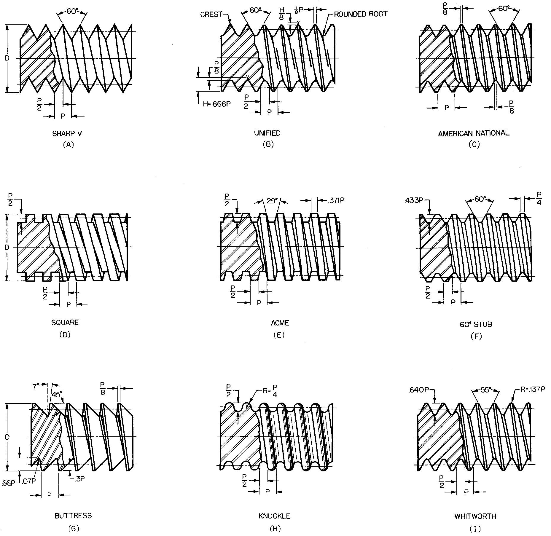
The Sharp V thread is used primarily for brass pipe work. However, it is rarely used because of the difficulty in producing sharp crests and roots.
The most commonly used thread form is the Unified.
This is the form which is used for the large majority of threaded fasteners. It is the standard form adopted in 1948 by the United States, Great Britain, and Canada. The Unified thread permits parts made in each of these countries to fit one another.
The American National thread differs from the Unified only in that the crests and roots are always flat. The crests on the Unified thread may be either rounded or flat, but the roots are always rounded.
The Square thread and the Acme thread are used on parts when force and power must be applied along the threaded portion.
Threaded parts used to transmit power are found on house jacks and on woodworking vises.
The Acme thread is a modified form of the Square thread and, incidentally, has generally replaced it. It is stronger and easier to make than the Square thread.
The 60° Stub form is a special purpose thread. It is often used in place of the American National thread in cases where the depth of the thread may be too deep.
The Buttress thread is used to transmit power in only one direction. It is useful for weight lifting devices, gun breech blocks, and soon.
The Knuckle thread is usually made by molding or by rolling it to shape. It is used largely for glass jars and for electric light bulbs and sockets.
The Whitworth thread is gradually being replaced by the Unified thread.
Forming internal screw threads
Screw threads are formed manually or mechanically. Regardless of the method, a hole must first be drilled, bored, or otherwise formed before internal screw threads can be formed. The drilled hole is referred to as a tap drilling.
The size of the hole depends upon the thread form and the nominal diameter of the desired thread. The tap drill size is always smaller than the major diameter of the thread.
Sufficient metal must be left for the threads. Selection of the proper size of tap drill is important, since an undersize tap drill would result in the breakage of taps because the tap would be forced to cut more metal than it is capable of doing.
Tap drill sizes for the Unified and American National thread series may be obtained from Table 8.
Threads may be cut manually with a hand tap in an operation called tapping. A tap is a hardened steel cutting tool which somewhat resembles the threaded part of a bolt. It consists of a thread, flutes which have cutting edges, and a shank, as shown in Fig. 12-29.
Fig. 12-29. A tap (5". W.)

The threads on the tap cut mating, or matching, threads in the work. The end of the shank is made square to fit a tap wrench or other driving device. The hand tap is caused to advance in the hole by turning it manually with a tap wrench.
As the tap winds into the work, threads are formed on the inner surface of the hole by the cutting edges of the tap.
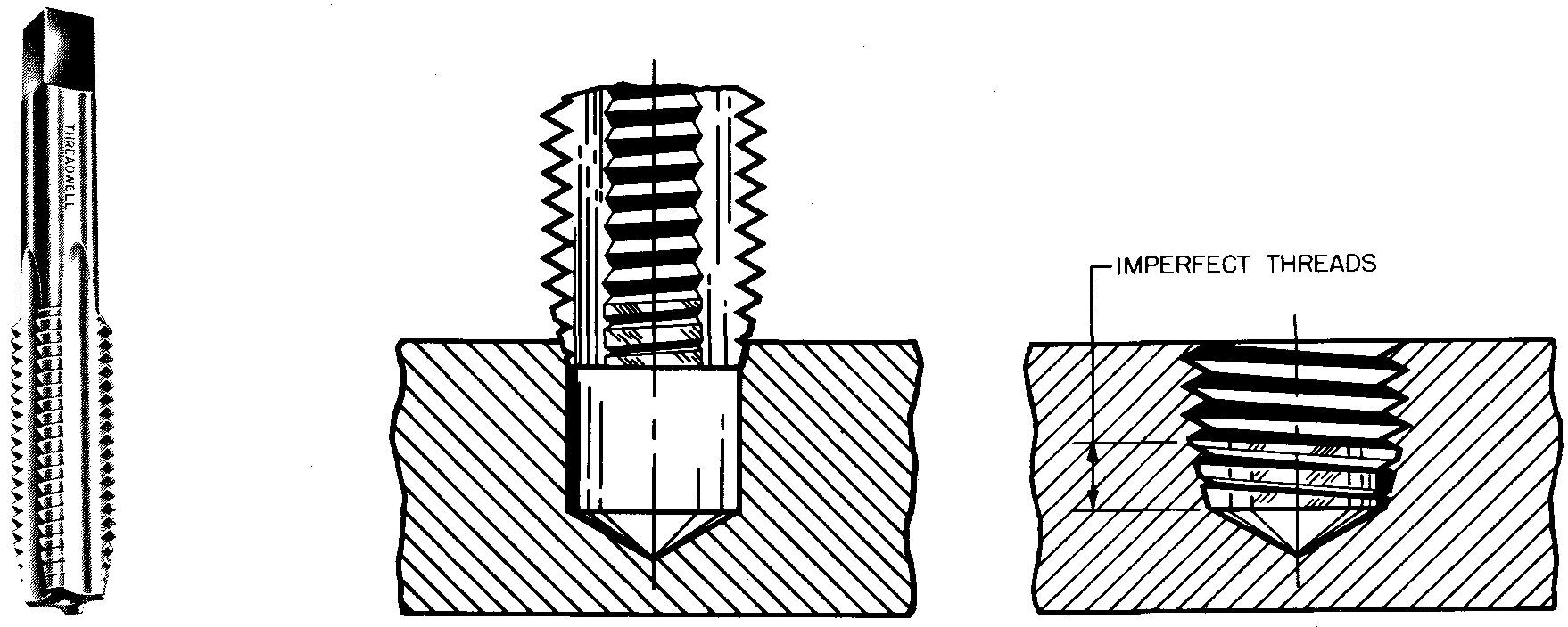
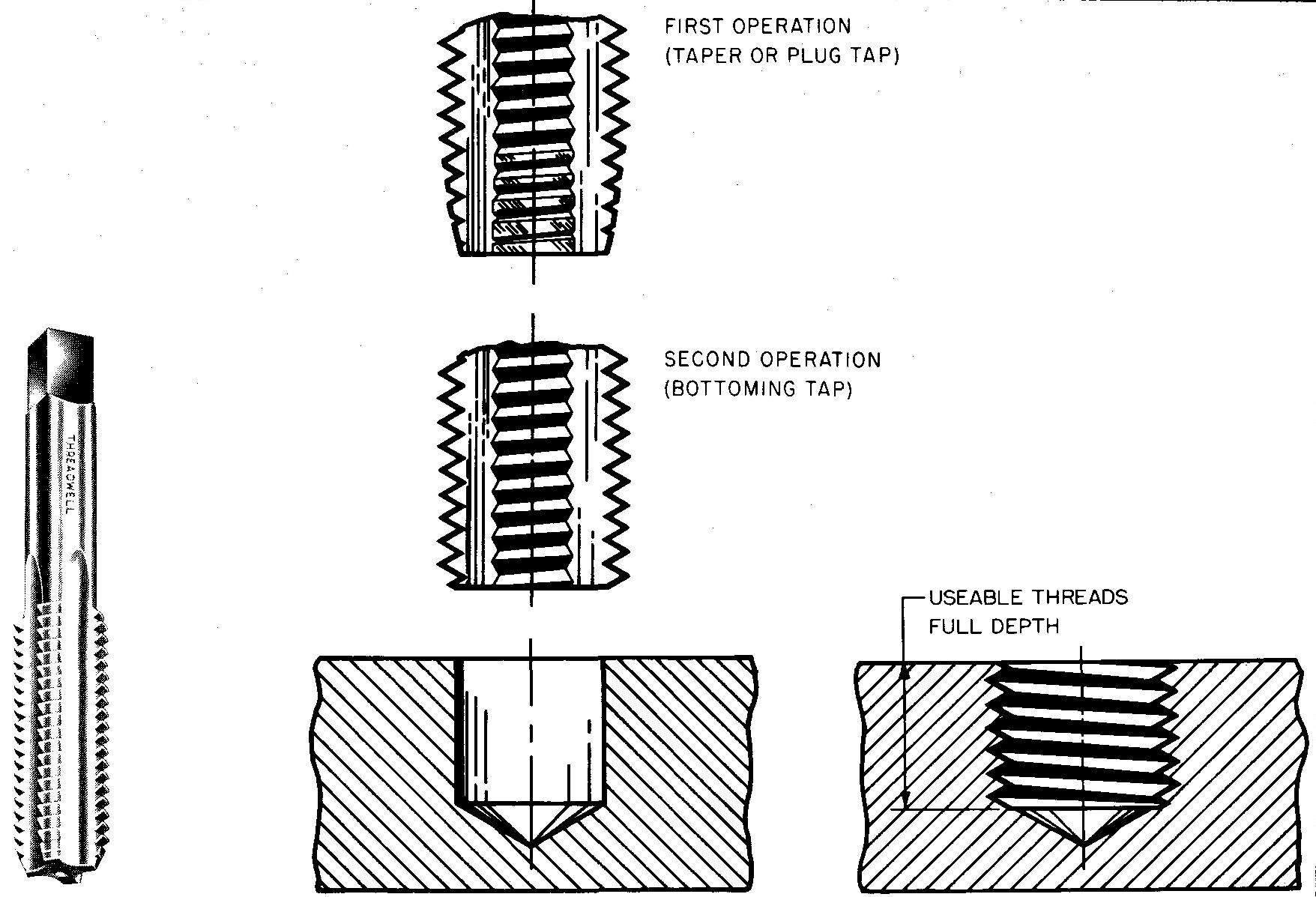
Three styles of hand taps, (taper, plug, and bottoming), their uses, advantages, and disadvantages are shown in Fig. 12-30.
Internal threads may also be cut mechanically on a tapping machine or on a lathe.
Fig. 12-30. Three styles of taps
TAPER HAND TAP Used for very hard metals. Long taper at ends permits easy starting of the tap in the drilled hole. Due to the taper on the end, the tap has from 3 to 4 imperfect threads. Holes cannot be threaded to full depth with this tap.
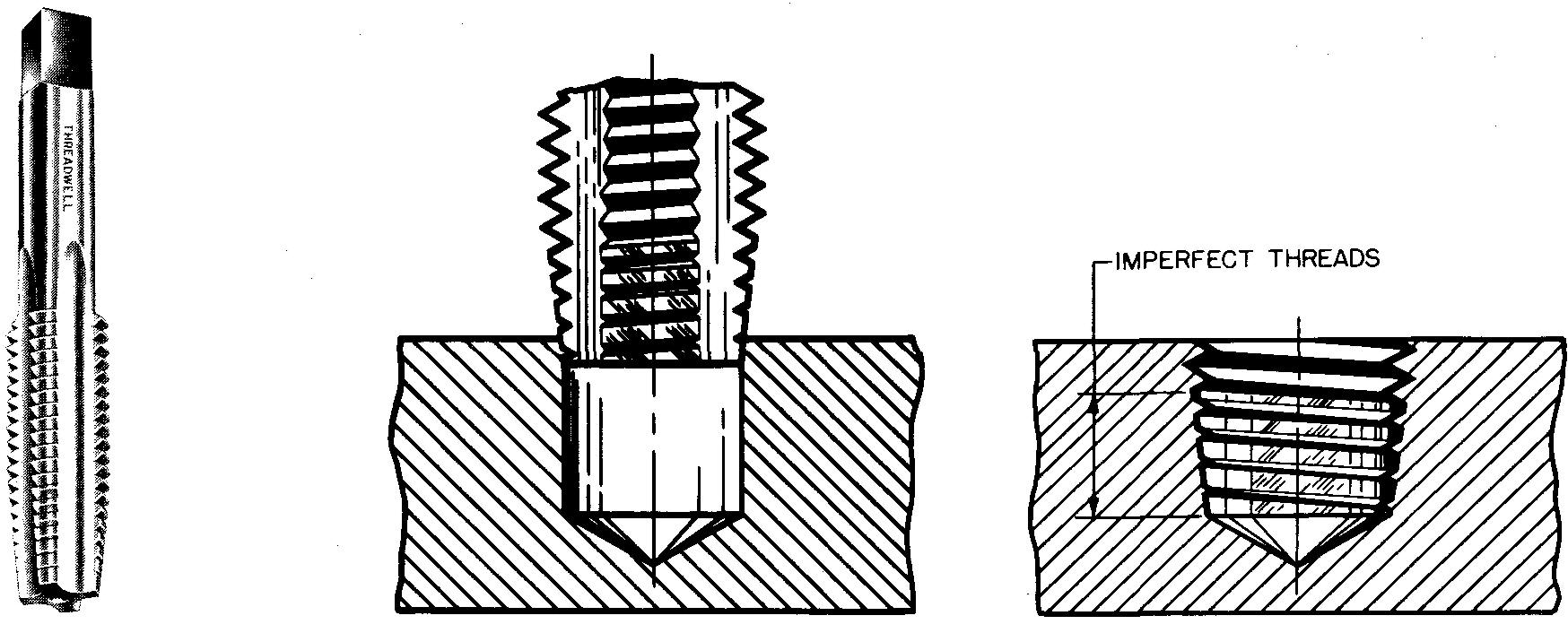
PLUG HAND TAP Used for general purposes such as holes for screw threads. Slight taper permits easy starting of the tap in a drilled hole. A slight taper on the tap causes imperfect threads. Holes cannot be threaded to full depth with this tap.
BOTTOMING HAND TAP Used for cutting threads to maximum depth. Threads can be cut to full depth of the drilled hole. This tap has no taper. A taper or plug tap must first be used to start the threads, followed by a bottoming tap.
The work is held in a chuck or fastened to a faceplate. Both a chuck and a faceplate are lathe attachments used for holding work.
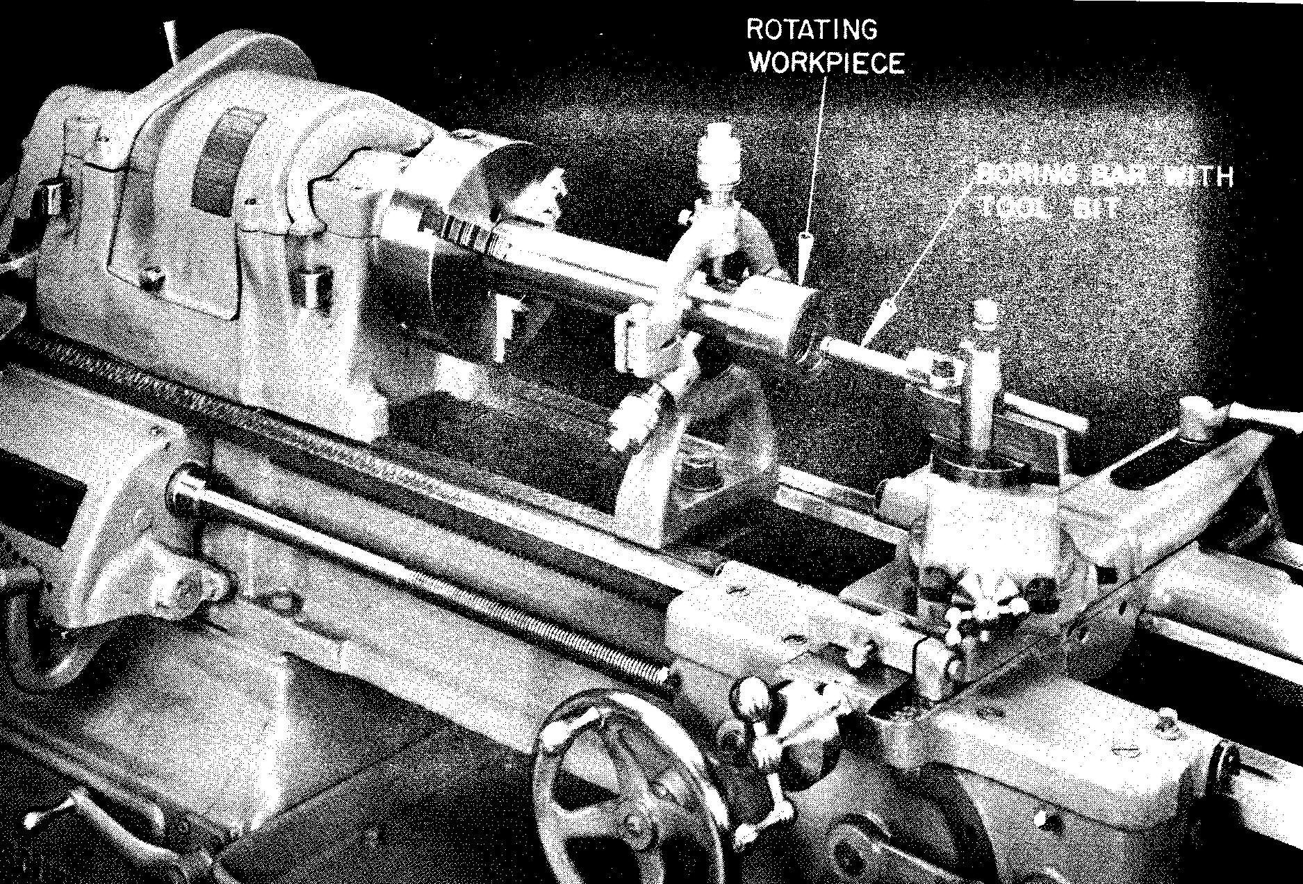
A hole is first drilled or bored to the proper size while the part is on the lathe. Next, a boring bar, which has a hardened steel tool bit ground to the required thread form and size, is brought into contact with the inner wall of the hole.
The work is caused to rotate, and the tool bit is automatically advanced into the hole, as shown in Fig. 12-31. The thread, consisting of a spiral ridge, is formed by the continuous action of the cutting tool.
Fig. 12-31. Cutting internal threads on a lathe
Forming external threads
Our studies will deal with two methods of forming external threads: cut threads and rolled threads.
Cut threads
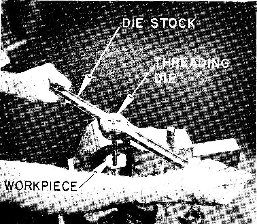
Threads may be cut on a cylindrical surface with a hardened steel cutting tool called a threading die. When a thread is being cut manually, a die stock is used.
The die stock consists of a frame to hold the die and handles for turning the die on the work, as shown in Fig. 12-32A. External threads may also be formed on an automatic screw machine by revolving thread ing dies. The die, shown in Fig. 12-32B, is held in a die holder and run on to the work, cutting the thread.
Fig. 12-32. Cutting external threads
(A) die stock and threading die
(B) threading dies
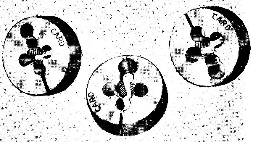
When the direction of rotation of the work is reversed, the die is drawn off by being opened automatically or by being unscrewed from the work.
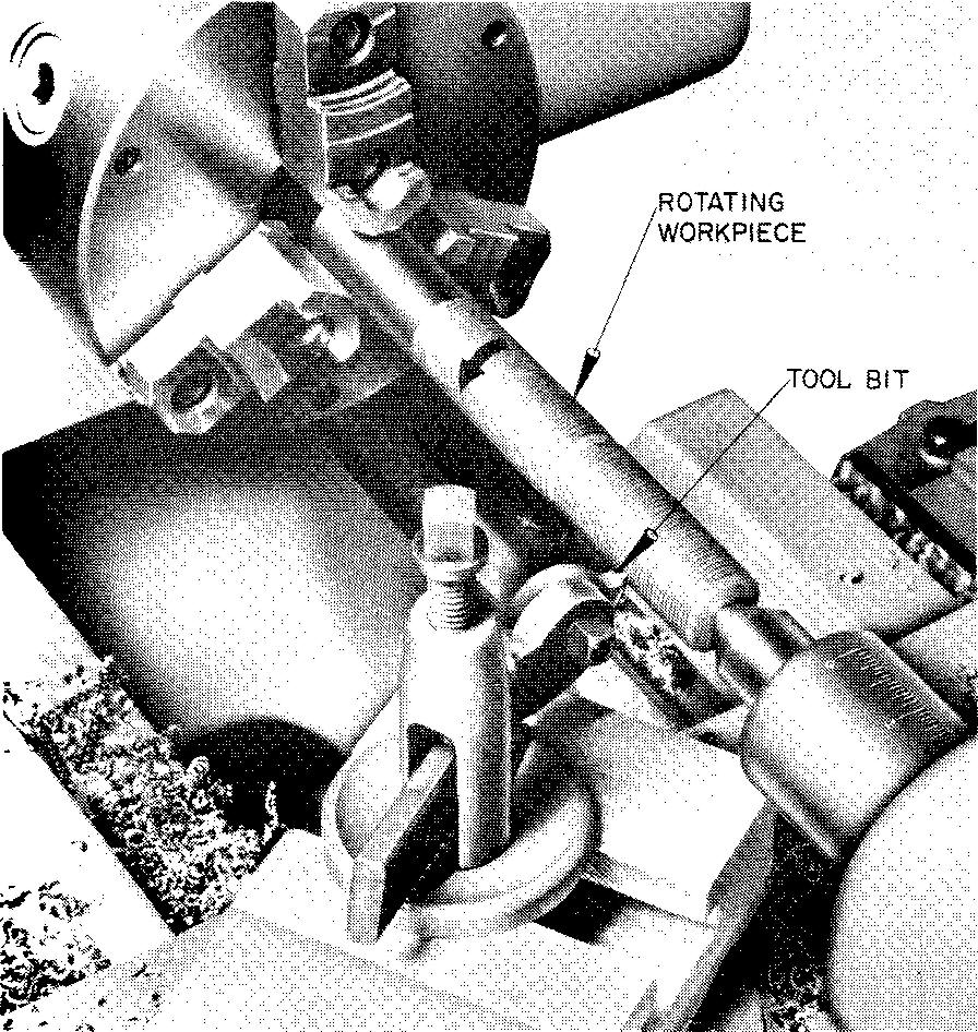
External threads may also be cut on a lathe. The work is held in a chuck or is fastened to a faceplate and is caused to rotate.
A tool bit, ground to the shape and size of the required thread form, is held in a tool holder. It is brought into contact with the rotating work.
The tool bit automatically advances parallel to the axis, or center line, of the work cylinder as the work rotates. A spiral cut is formed, leaving ridges, which are the thread, as shown in Fig. 12-33. rolled threads
Fig. 12-33. Cutting external threads on a lathe
Rolled threads
The thread rolling process consists of pressing hardened steel blocks called dies firmly against the surface of a plain cylindrical rod. The rod is caused to rotate and to advance between the dies. In this way, the dies squeeze the thread form onto the cylindrical surface, as shown in Fig. 12-34.
Fig. 12-34. Thread rolling
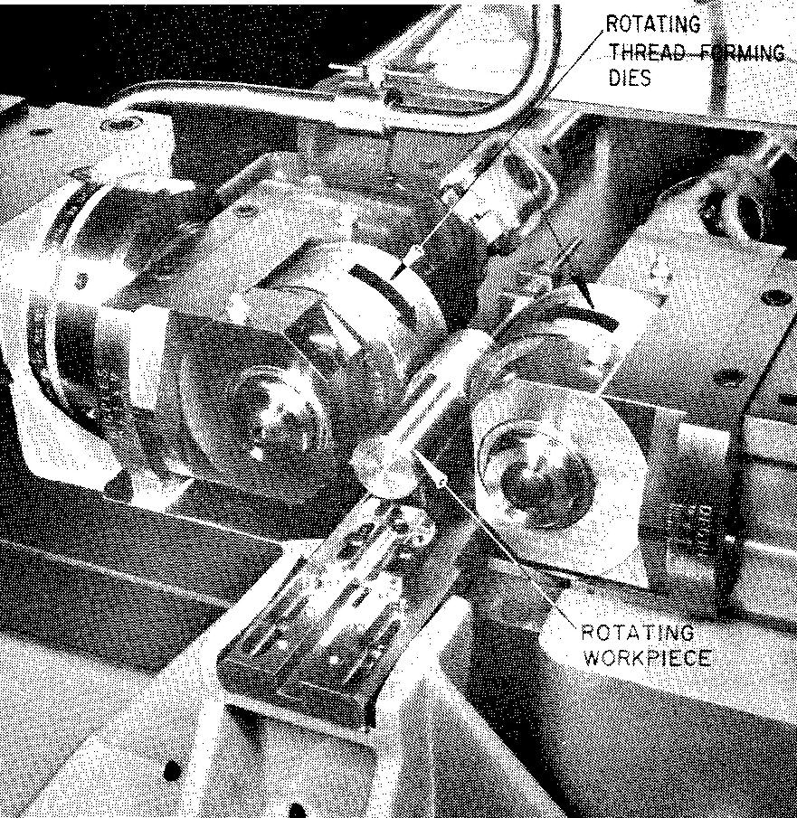
The working faces of the dies are made with a threaded form which is the reverse of the thread to be produced. Threads are produced by this method on special thread rolling machines.
"Rolled threads, when compared to cut threads, have increased strength, greater accuracy, and a high degree of surface finish. They are uniformly produced at high rates of productivity with no wasting of material. The bulk of commercial screw threads are made today by the rolling process."
Screw thread representation
There are two methods of representing threads on a drawing, depending upon the size.
Threads measuring less than 1 inch diameter are drawn symbolically.
Threads measuring 1 inch diameter or more are sometimes drawn as detailed thread forms.
Drawing symbolic threads
When this method is used, the actual thread form, or profile, is not accurately drawn. It may be represented as a schematic thread symbol or as a simplified thread symbol.
The simplified thread symbol saves considerable drafting time and is used mostly for detail drawings.
The schematic thread symbol is used for both detail and assembly drawings.
The use of the two symbols for representing threads varies with individual company standards. Draftsmen should be familiar with both methods because of their wide usage.
Figure 12-35 shows schematic symbols and Fig. 12-36 shows simplified symbols for representing both external and internal threads.
Fig. 12-35. Schematic thread symbols
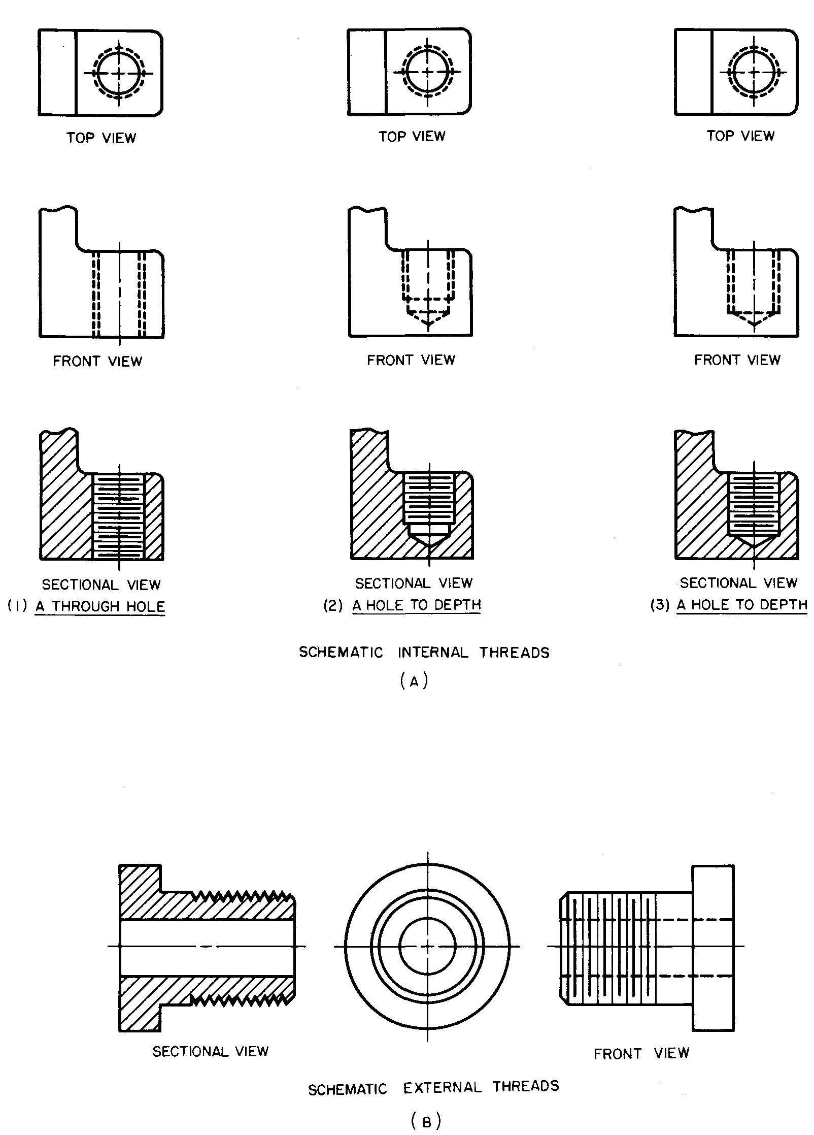
Fig. 12-36. Simplified thread symbols
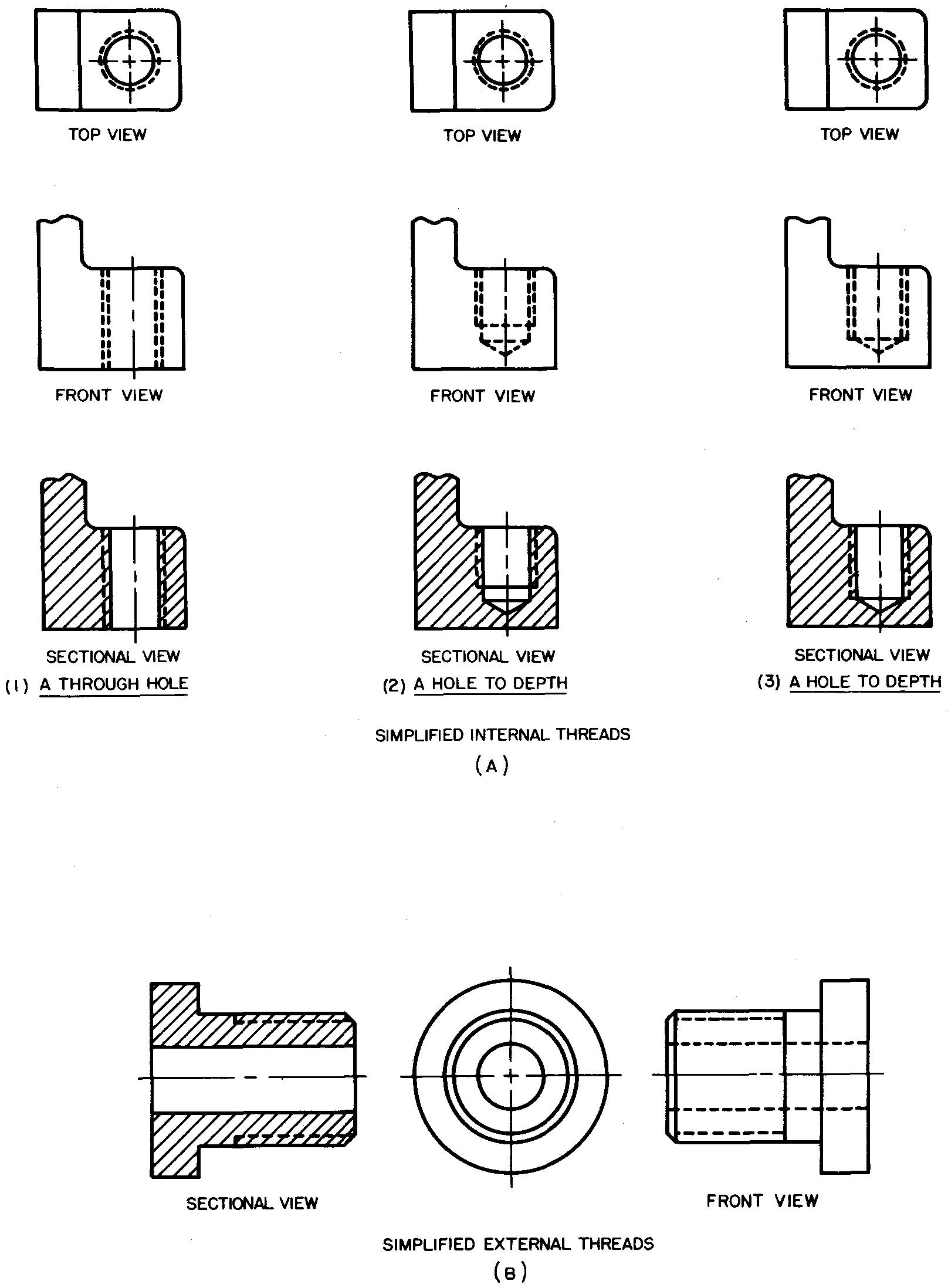
All thread forms are shown on the views in the same way and are identical in appearance. Since the thread form cannot be identified by the way it is represented on the drawing, it is specified in a note. Only the thread length and the major diameter are drawn to scale.
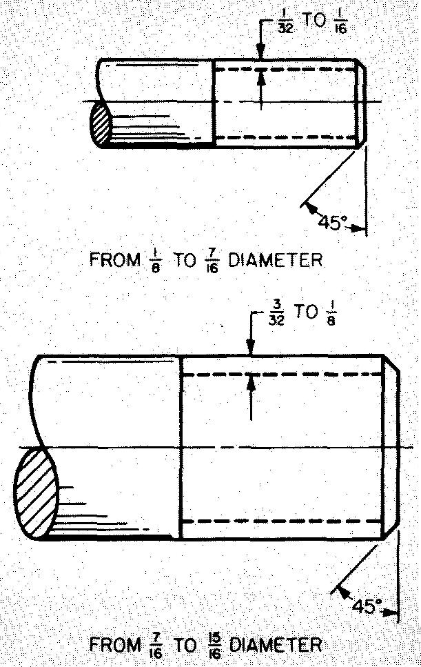
All the other thread features are approximated. To aid in drawing various size threads to a consistent proportion, it is suggested that threads with a major diameter of 1/8 inch to 7/16 inch be drawn with a pitch of approximately 1/32 inch to 1/16 inch.
Threads with a major diameter of 7/16 inch to 15/16 inch should be drawn with a slightly larger pitch of 3/32 inch to 1/8 inch.
For drawing purposes, the depth of thread is always equal to one-half the pitch. The chamfer on the end of an external thread is generally drawn at an angle of 45°.
The length of the chamfer is usually made equal to the pitch of the thread. The chamfer consists of a circular beveled cut which aids in engaging one threaded part with another.
Figure 12-37 illustrates the general proportions for drawing schematic threads. Figure 12-38 shows proportions for simplified threads.
Fig. 12-37. Drawing proportions for schematic threads
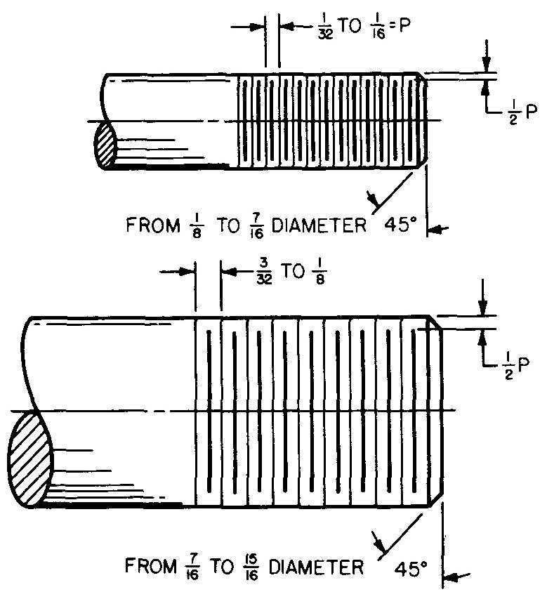
Fig. 12-38. Drawing proportions for simplified threads
Drawing detailed thread representations
Threads measuring more than 1 inch diameter are usually drawn in detailed thread representation. This type of representation is used mostly for assembly drawings. The procedure for drawing detailed threads is much the same for all thread forms.
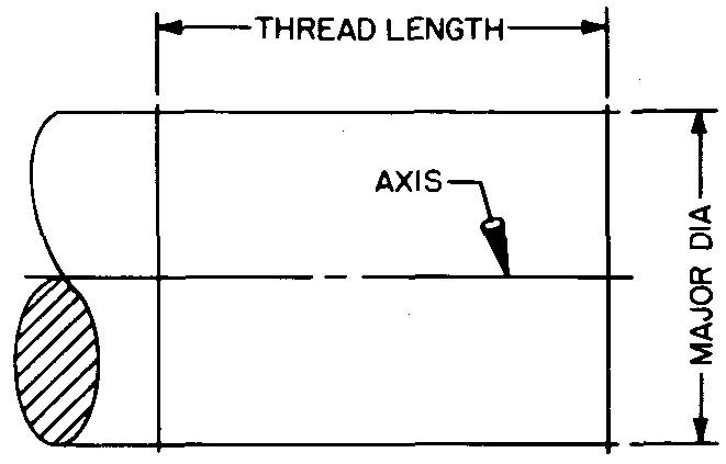
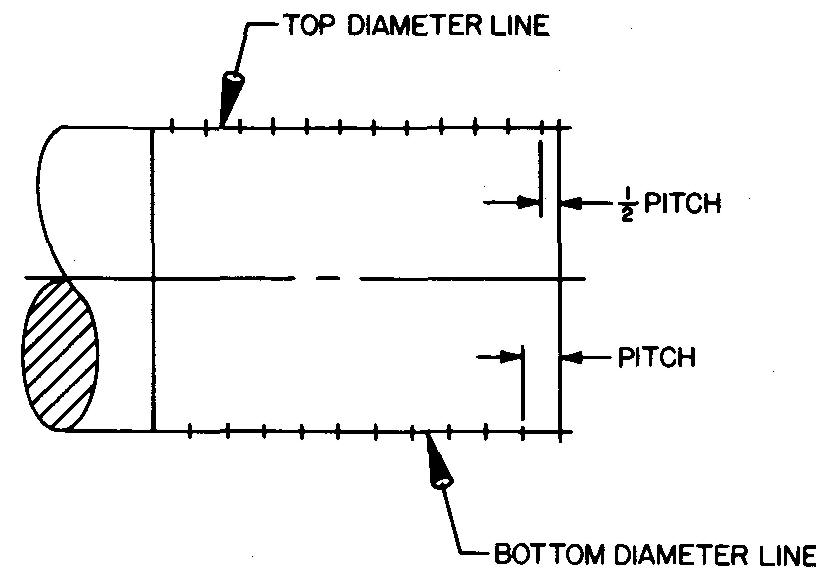
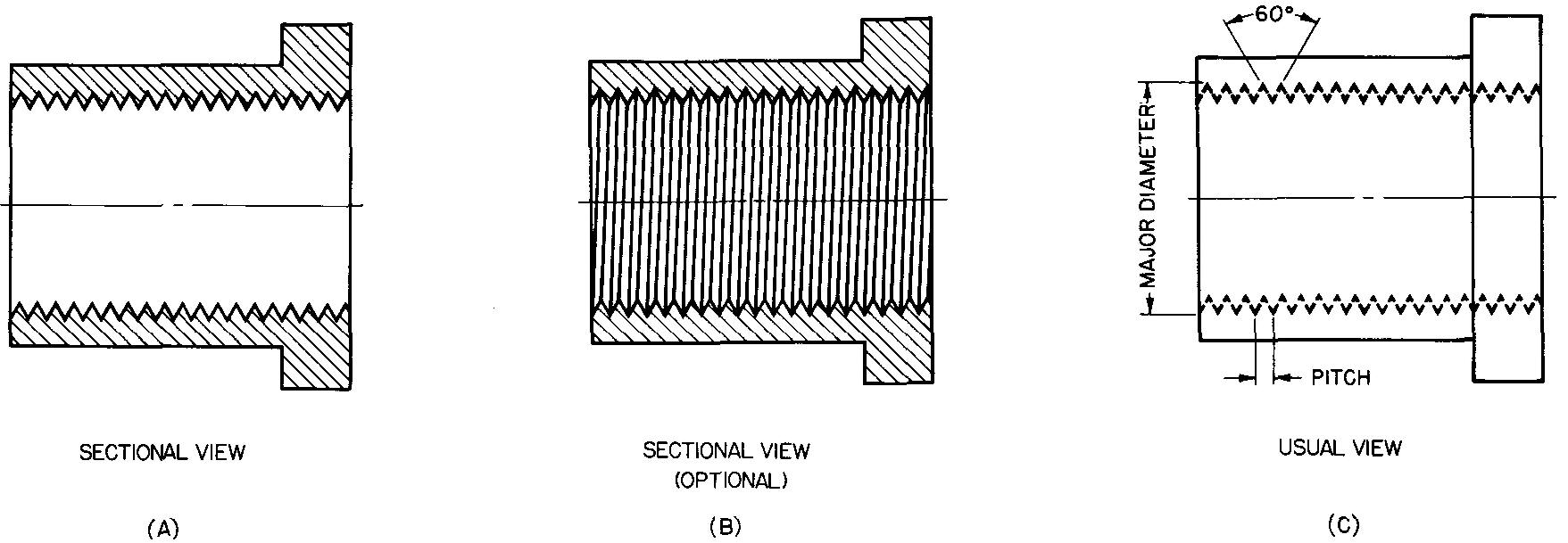
Figure 12-39 illustrates the method of drawing a single, left hand (LH), external Sharp V thread. Figure 12-40 illustrates right hand (RH) internal threads which are drawn in much the same way.
Fig. 12-39. Procedure for drawing external detailed threads
STEP 1 — Lay out the axis, the major diameter, and the length of thread.
STEP 2 — Lay off the pitch on the bottom diameter line. (For single threads the pitch and lead are equal.) On the top diameter line start with one space equal to l/2 pitch followed by spaces equal to full pitch.
STEP 3 — Draw the 60° thread form
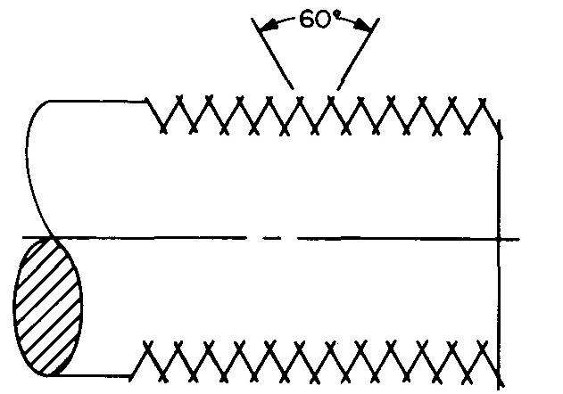
STEP 4 — Connect the crest and root lines. Darken in the final lines. Threads shown are left hand.
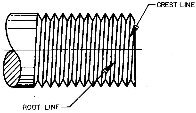
Fig. 12-40. Internal detailed threads
Thread series for unified and national screw threads
Thread series is a term referring to the number of threads per inch for a given diameter, or more simply, the fineness or coarseness of a thread.
There are six series of screw threads for the Unified and American National threads. Letter symbols used in explaining the six series are as follows:
UN — Unified, F — Fine, N — National (American)
EF — Extra Fine, C — Coarse, S — Special
Coarse thread series
This thread series is designated UNC (for Unified Coarse) or NC (for National Coarse). This series is used for the great majority of machinery purposes.
Ffine thread series
The thread series designated UNF or NF is used for the great majority of automotive and aircraft work.
Extra-fine thread series
The thread series designated UNEF or NEF is used where conditions require a shallow thread, as on thin walled tubes.
8-thread series
The thread series designated 8UN or 8N is used for conditions requiring high pressures, such as cylinder heads, pipe flanges, and so on. All threads in the 8-Thread Series run 8 threads to the inch.
12-thread series
The thread series designated 12N is used where conditions require the threading of thin parts when it is essential to provide many threads in a limited distance.
16-thread series
This thread series is designated 16UN or 16N. It is used for conditions which require fine adjustments, as for ball bearing retainers, adjusting collars, and so on.
Special thread series
Some companies use a seventh series: the Special Thread Series, designated UNS or NS.
Threads in this group include nonstandard, or special, combinations of screw thread diameter, pitch, and length of engagement.
This group is used for a wide variety of special conditions.
Classes of fit for unified and american national screw threads
There are three classes of thread fit:
Class; 1, loose; Class 2, medium; and Class 3, thigh
The number tells the shopman how loosely (or tightly) a threaded part must fit.
Letter symbols after the thread-fit class -number are used to indicate an internal or external thread.
Such symbols are generally reserved for notation used for views on assembly drawings. Many companies omit internal or external letter symbols on detail drawings.
A — External Threads B — Internal Threads
classes 1A and 1B : loose threads
Threads of this class of fit are used primarily in ordnance work and in other cases where free assembly of mating parts is important. This class includes the widest allowance and tolerance for the mating parts.
classes 2A and 2B : medium threads
This is the most commonly specified class of thread fit. It is used widely in the production of bolts, screws, nuts, and so on. A moderate allowance is given to insure minimum clearance between mating parts.
classes 3A and 3B : tight threads
This class of thread fit is specified only where accuracy and closeness of mating parts are important. No allowance is provided, resulting in tight threading conditions.
Dimensions for drawing threaded (or tapped) holes
Recommended depths for drawing the tap drill and the threaded hole may be found by-using the table in Fig. 12-41.
Fig. 12-41. Dimensions for threaded holes
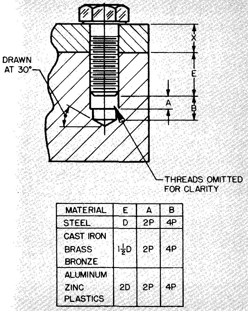
The figures in the table refer to all thread sizes. All sizes take into account the material to be threaded and the diameter of the fastener. Dimensions obtained from the tables may be rounded off to the nearest sixteenth of an inch to simplify drawing.
The student should observe that dimension E (thread engagement) plus dimension X equals the bolt length. Dimension E must, therefore, be adjusted slightly in cases where it would not conform to available lengths of commercial fasteners.
Available lengths of commercial bolts and screws are found in Table 29.
It must be understood that the dimensions in Fig. 12-41 are only approximate. They are considered accurate enough for most drawing purposes.
Specifying threads on drawings
Screw threads are specified by a note which consists of certain numbers, words, and abbreviations.
The method of notation and an explanation of the symbols which are used to specify internal threads is shown on the drawings in Fig. 12-42. Illustrations are given for both the American National thread and for the Unified thread.
Fig. 12-42. Specifying internal screw threads
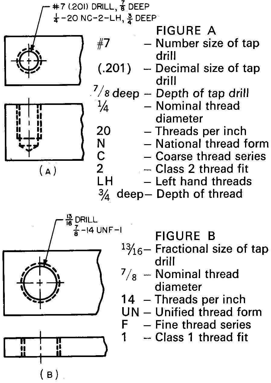
Notice the tap drill size is given in both cases. Individual company standards differ on this point, since some companies prefer to leave the selection of tap drill size to the shopman.
The method of notation and explanation for external threads on a drawing is shown in Fig. 12-43. The length of the thread may be specified either in the note or by a dimension placed near the view.
Fig. 12-43. Specifying external screw threads
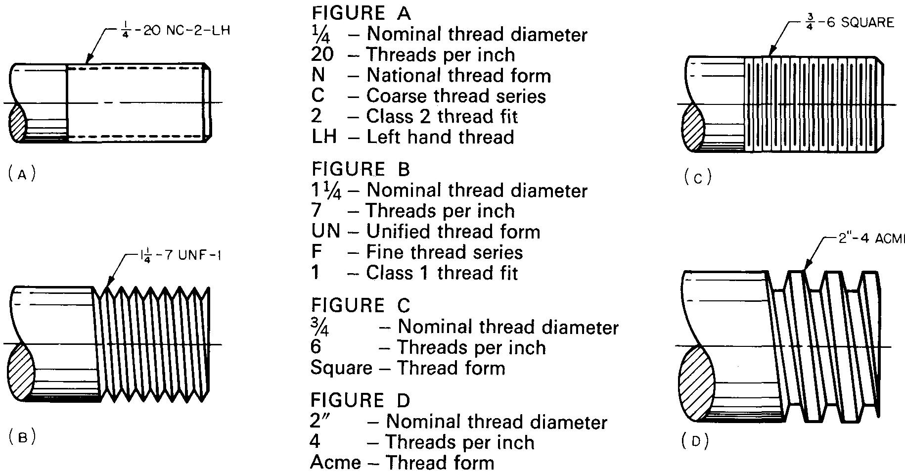
When precision threads are required, the three-wire method is specified, as in Fig. 12-44.
Fig. 12-44. Three-wire method
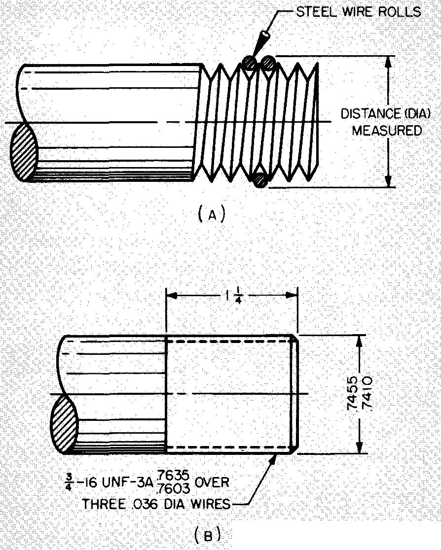
Three accurately sized steel wire rolls are held in the spaces between the thread, and the distance across is measured with a micrometer.
The draftsman specifies the size of the rolls and the required distance across the rolls as shown at B. Parts requiring fine adjustment, as in the design of instruments, require precision threads.
Under ordinary circumstances, however, it is sufficient to specify external threads as shown in Fig. 12-43.
Reaming
The process of enlarging a round hole, previously made by drilling or boring, is called reaming. Reaming finishes the hole to a precise size and makes it straight, cylindrical, and smooth.
The tool which is used is called a reamer. There are many different styles of reamers, as shown in Fig. 12-45.
Fig. 12-45. Various styles of reamers
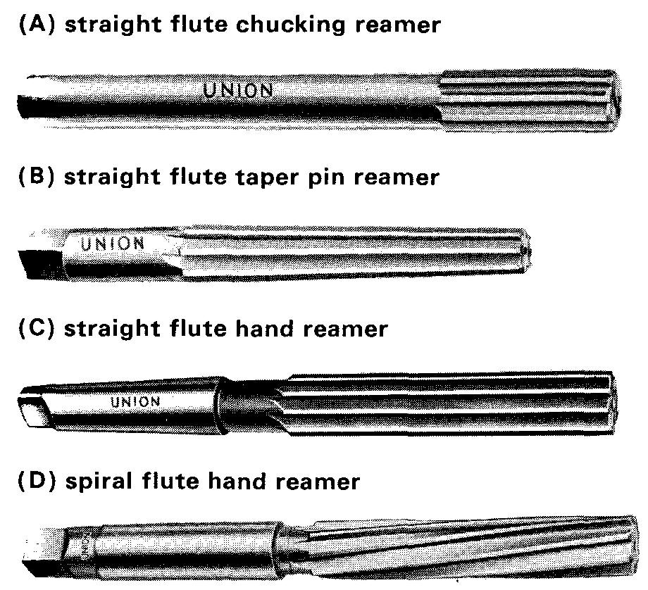
Basically, a reamer is a cutting tool consisting of either straight or spiral flutes which form the cutting lips. The reamer has a shank which may be straight or tapered, depending upon the driving mechanism.
Reamers are hard and brittle. If forced to cut too much stock, a reamer may break. Reamers are generally limited to the removal of not more than 1/64 inch of stock from the diameter of a hole.
Reamers may break if forced to cut to the full depth of a blind hole. For a blind hole, the drilled hole is intentionally made slightly deeper than the reamed hole. If it is practical, the drilled hole is drilled all the way through.
Manufacturers have established a working tolerance (or limits of accuracy) for reamers, depending upon the diameter, as shown below. This table is particularly useful when a shaft or pin is being fitted into a reamed hole.
Diameters up to 1/2 inch = +0.0005 to -0.0000
Diameters from 1/2 to 1 inch = +0.0010 to -0.0000
Diameters of 1 inch and larger = +0.0015 to -0.0000
For example, it would not be possible to have a dowel pin (an accurately sized steel cylinder) measuring exactly 0.5000 inch in diameter fit tightly into a 1/2-inch reamed hole.
By consulting the table we find the reamed hole may measure as much as 0.0010 inch oversize. If the hole is reamed to maximum tolerance, the pin would fit loosely in the hole. The solution, of course, would be to select a slightly larger size dowel pin.
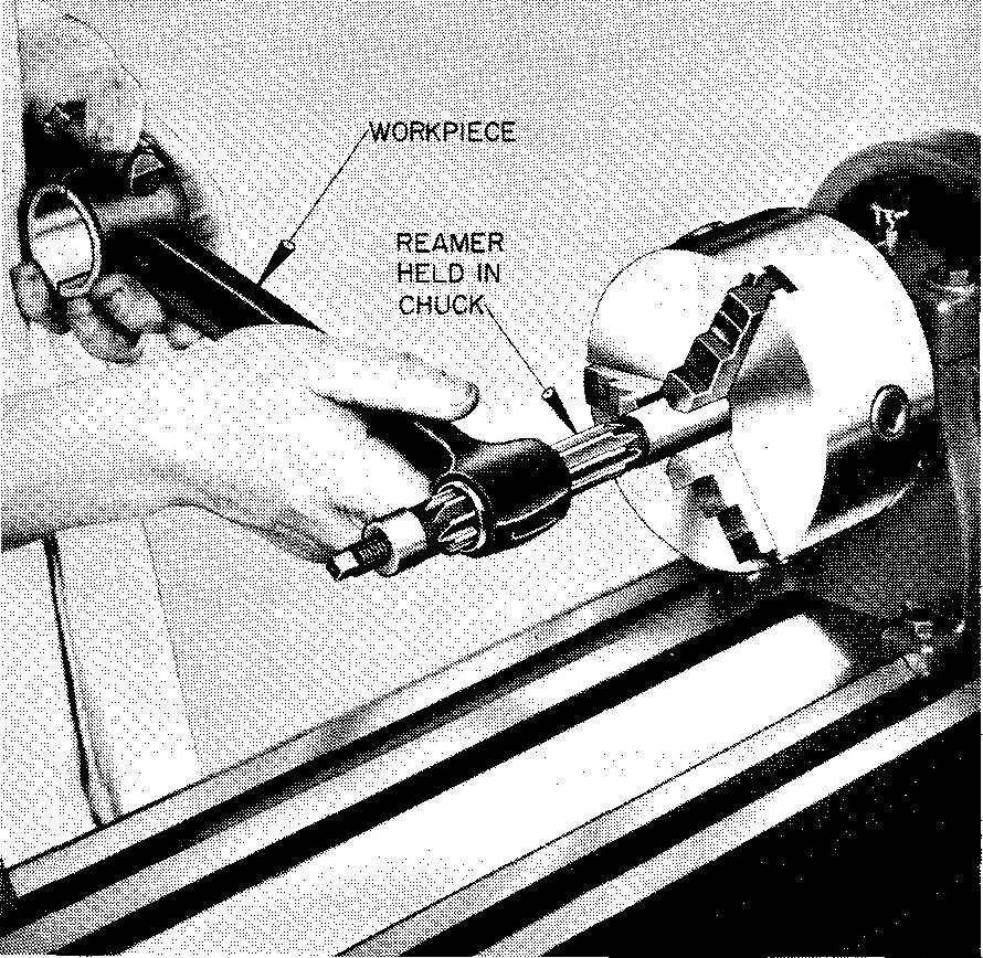
Small quantities of holes are often reamed manually, using a tap wrench and a hand reamer. Large quantities of holes, on one or more similar parts, are generally reamed mechanically on a drill press; on a lathe, as shown in Fig. 12-47; or on an automatic screw machine.
Fig. 12-47. Reaming a hole on a lathe
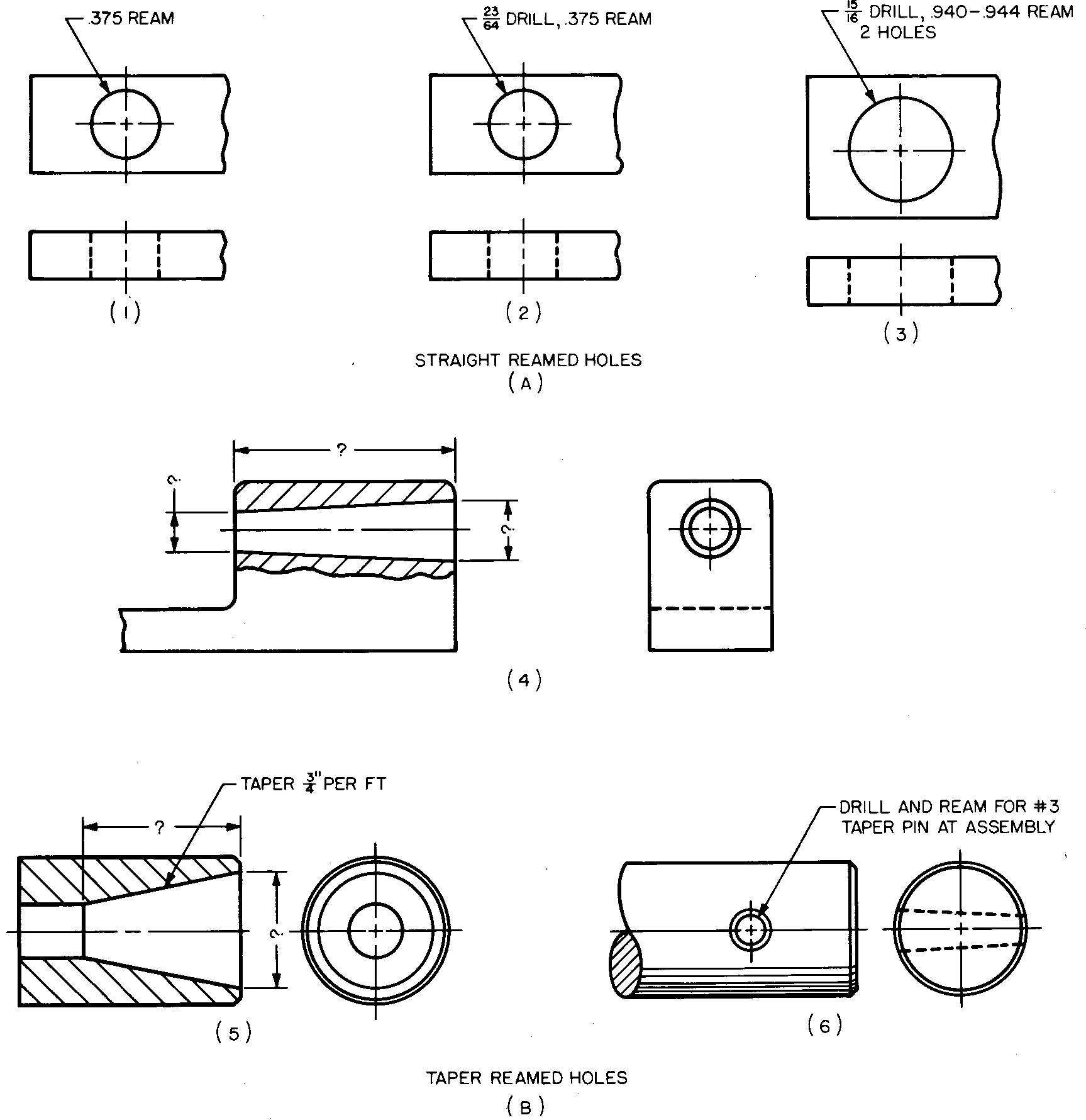
Holes may be reamed with either straight or tapered walls, depending upon their in tended use. Reamed holes are commonly made for the installation of dowel pins and shafts, and in other cases when precision assembly of parts is required. The size of reamed holes can be accurately controlled.
The size of reamed holes may be specified on a drawing either in decimal or fractional form. Specifying the size of the drill which must precede the reaming operation is usualy optional.
This is another case where different companies may vary in their requirements. The three views in Fig. 12-48A illustrate the varying ways in which to specify a straight reamed hole. The views in Fig. 12-48B illustrate three common methods of specifying tapered reamed holes.
Fig. 12-48. Specifying straight and tapered reamed holes
Slots and Grooves
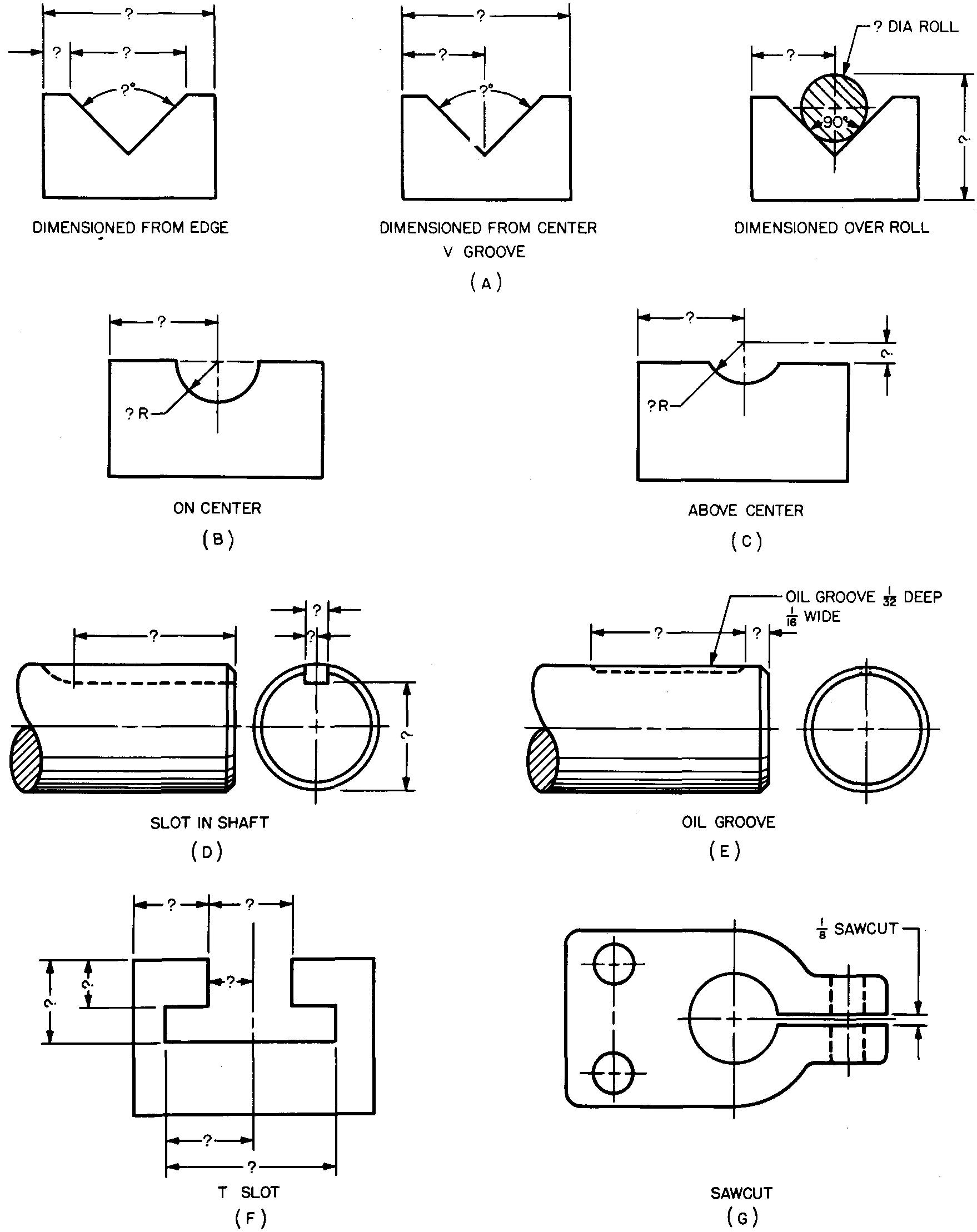
Slots and grooves are generally produced so that two different parts may fit together. Methods of manufacturing slots, flats, and grooves are shown in Figs. 12-49 and 12-50. Figures 12-51 and 12-52 show typical slots and grooves and methods of dimensioning.
Fig. 12-49. Cutting slots and grooves
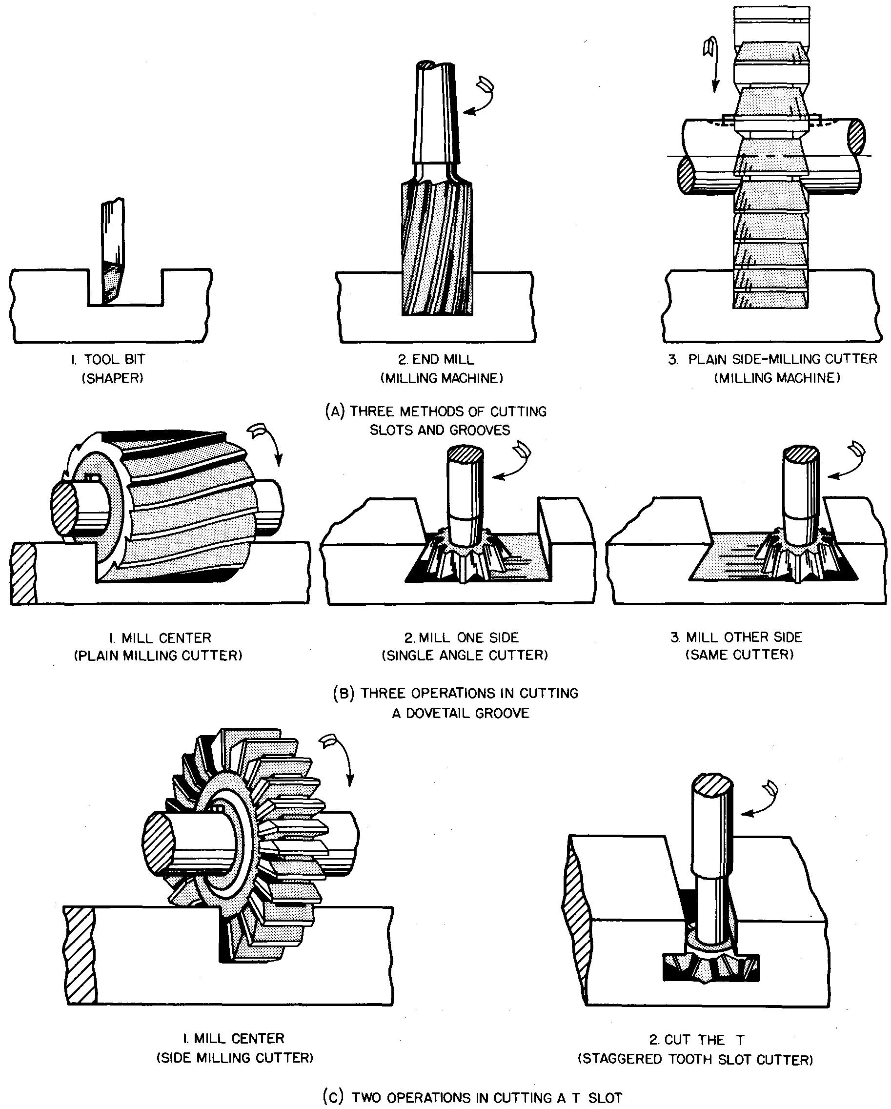
Fig. 12-50. Cutting slots and grooves
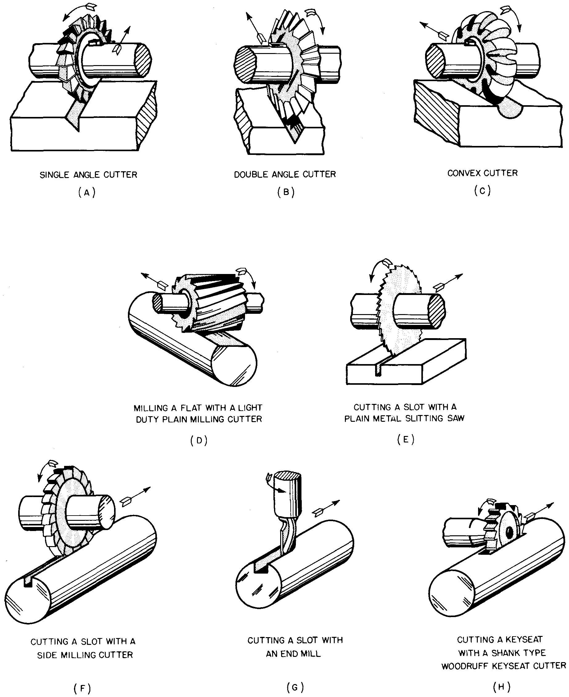
Fig. 12-51. Dimensioning slots and grooves
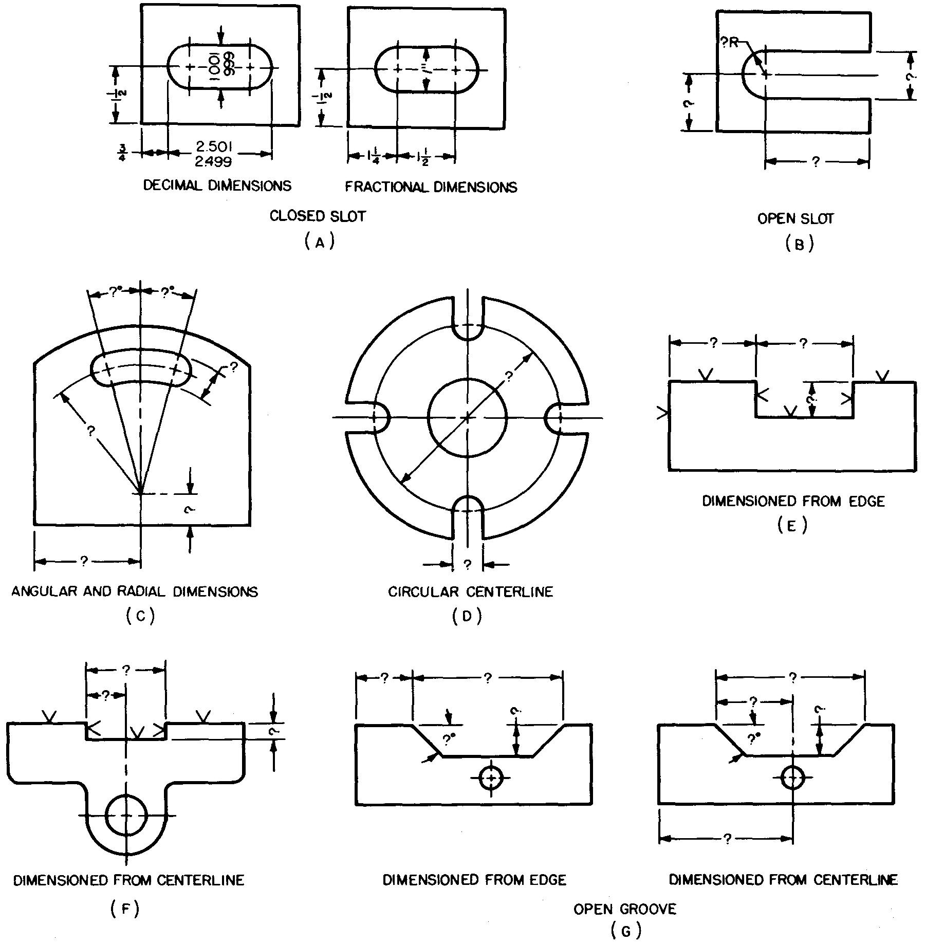
Fig. 12-52. Dimensioning slots and grooves
Dovetail tongues and slots
Dovetail slides are used on precision machines. They permit a sliding movement, but limit excessive side movement. Often slides are held in alignment by angular sides called dovetail angles.
A gib on one side permits adjustments to control smoothness of operation.
Over rolls method (Measuring Dovetail Slides)
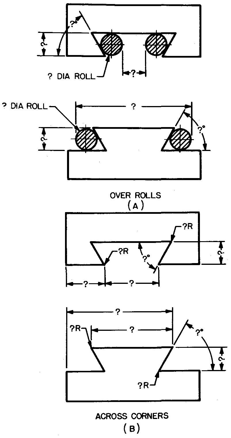
Rolls are used as a method of checking and inspecting the size of dovetail tongues and slots which have been machined. Rolls are short lengths of accurately sized steel cylinders.
They are held against the sides of the V slots, and the dimension across or between the rolls is accurately measured with a micrometer, as shown in Fig. 12-5 3A.
Fig. 12-53. Dimensioning dovetail tongues and slots
Alternate method
Another frequently used method of dimensioning dovetails is shown in Fig. 12-53B.
Tapers
Figure 12-54 illustrates methods of dimensioning parts which have tapers. The size of tapers may be specified by a dimension at both the small and large ends, as in Fig. 12-54A; by a note and a dimension at one end only, as in Fig. 12-54B; or by dimensioning one end and the angle, as in Fig. 12-54C.
Fig. 12-54. Dimensioning tapers
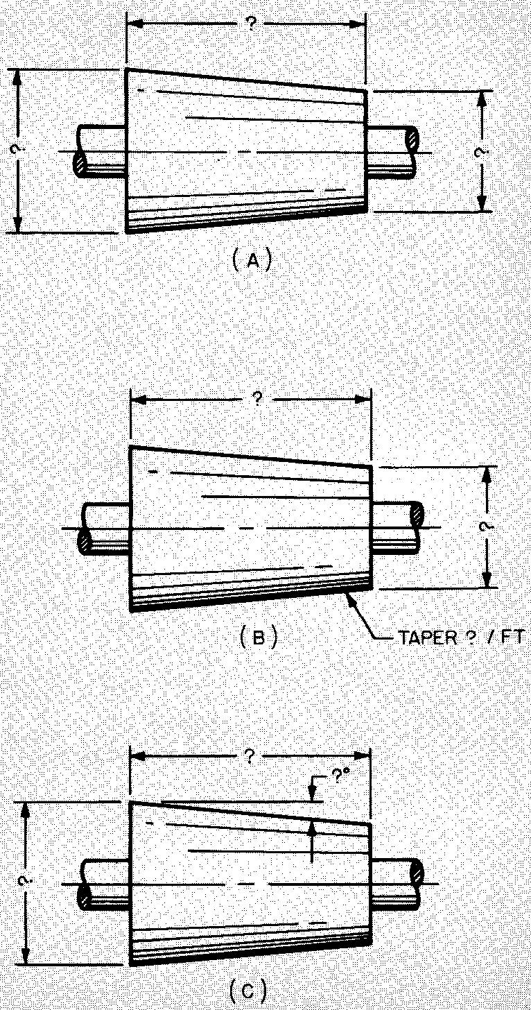
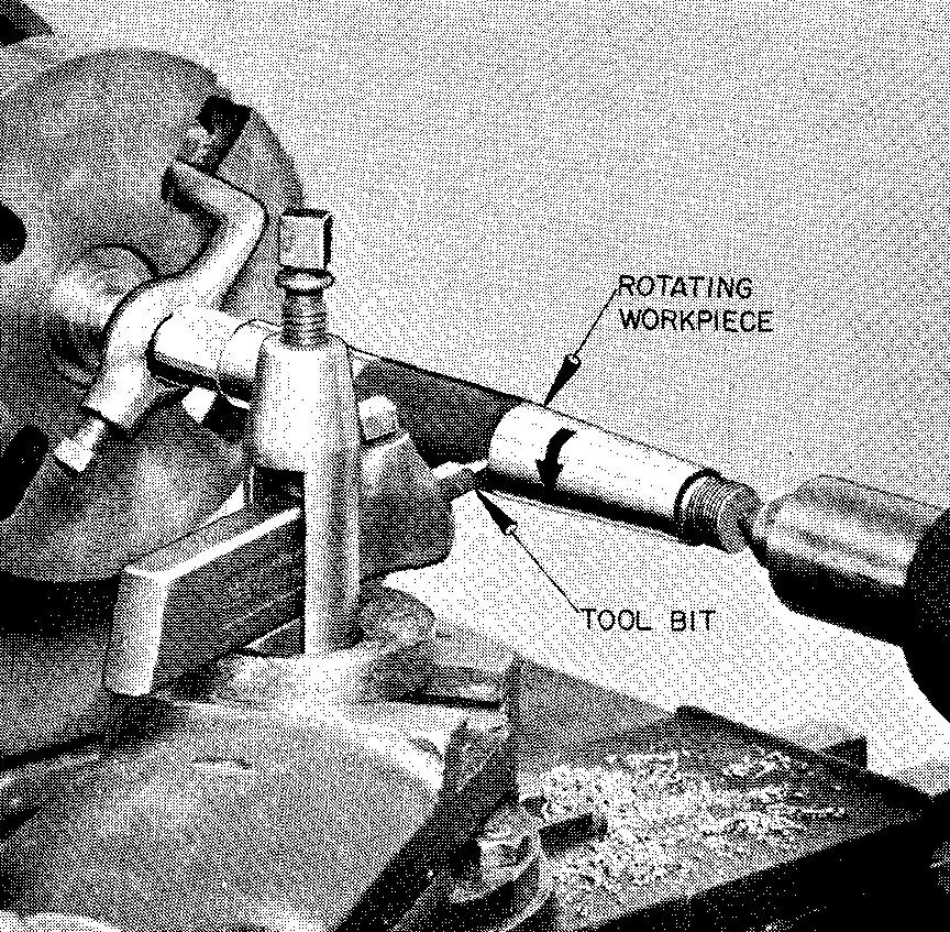
In each case, the total length of taper must be indicated. Fig. 12-55 illustrates a taper turning operation on a lathe. Taper per foot is used to describe long tapers. Taper per inch is used to describe shorter tapers.
Fig. 12-55. Turning a taper
Chamfers
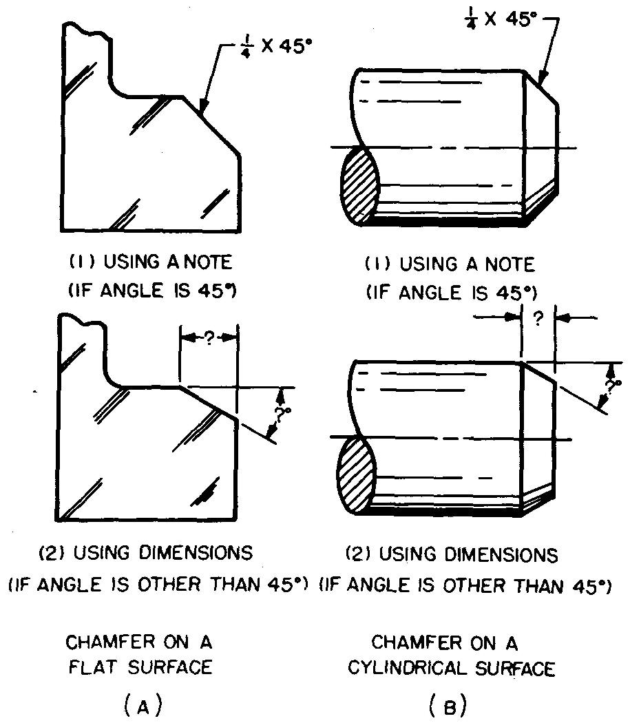
A beveled cut on an external corner of a part is called a chamfer. Ends of shafts, dowel pins, and threaded parts are usually chamfered to permit free entry of one part into another.
Chamfers may be specified by either a dimension or a note, as shown in Fig. 12-56.
Fig. 12-56. Specifying chamfers
Reliefs
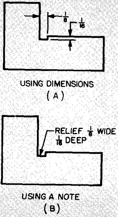
A small groove which lies below two adjacent surfaces is called a relief.
When two different surfaces intersect to form a corner, a small fillet (or curve) is formed, due to the inability of the cutter, grinding wheel, or tool bit to make an absolutely square corner. In some cases it is necessary to remove this curve. Reliefs are specified by dimensioning or by a note, as shown in Fig. 12-57.
Fig. 12-57. Specifying reliefs
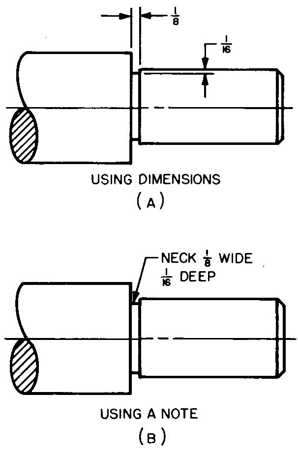
Necks
A small external groove cut on a surface of a cylindrical part by a lathe is called a neck.
It is made for the same purpose as a relief. Necks may be specified by dimensioning or by a note, as shown in Fig. 12-58.
Fig. 12-58. Specifying necks
Thread reliefs
Fig. 12-58. Specifying necks


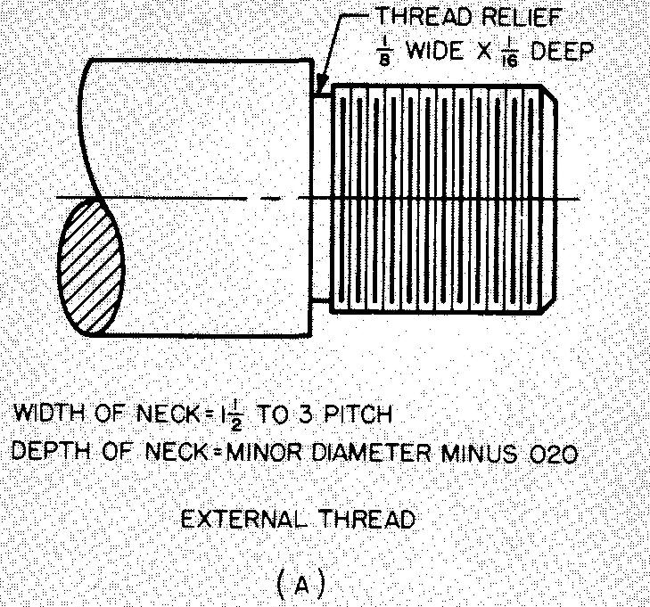
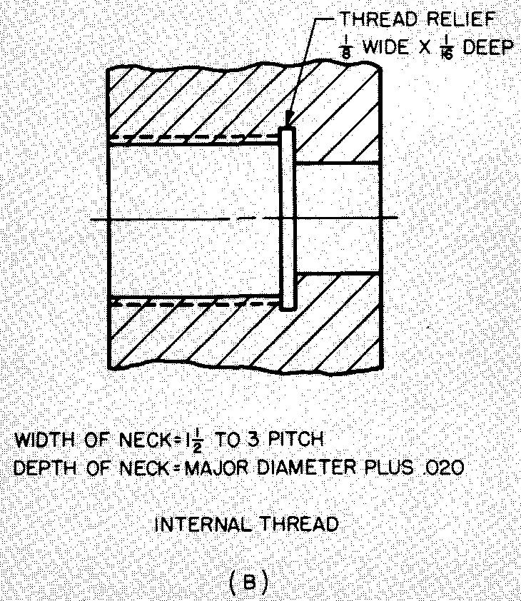
A form of neck usually made at the shoulder end of an external thread, as shown in Fig. 12-59A, is called a thread relief.
Thread reliefs are also produced at the end of a threaded hole to remove imperfect threads when it is necessary to screw a threaded part as far into a hole as possible, as shown in Fig. 12-59B. Thread reliefs are usually specified by note only.
Fig. 12-59. Specifying thread reliefs
Recesses
A recess may be either an external or an internal groove. On flat surfaces, the recess is an external groove which lies below one or more surfaces of the work as shown in Fig. 12-60A.
Fig. 12-60. Specifying recesses


It may be produced by machining or by casting. A recess on the walls in a cylindrical hole, as shown in Fig. 12-60B, may also be called an internal groove.
If the recess in this particular case is especially long, it is sometimes referred to as a chamber. The chamber may be made by casting or by cutting with a special recessing or boring tool on a lathe.
A recess is made for the purpose of reducing the bearing surface of one part moving in another, as a shaft which rotates in a hole.
Splines
Splines, or feathers, are shown in Fig. 12-61.
Fig. 12-61. Splines
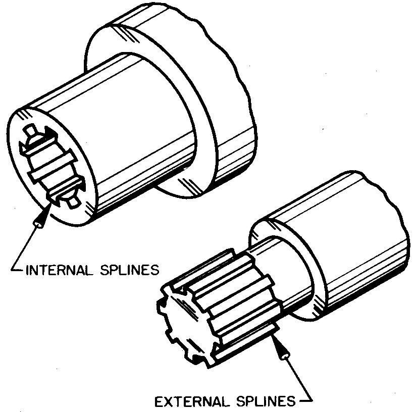
Splines are used to assemble a pulley or a flywheel to a shaft. The use of splines permits the parts to slide freely lengthwise along the shaft, but prevents the rotation of one part about another.
The splines may be machined
from either the shaft or the hub, or they may be made as separate pieces, in
which case they are usually fastened to the sliding part. Hobs and gear-shaper
cutters are used to cut the splines on shafts, while broaches or shapers are
used for cutting the teeth on the internal part.
12.31 flats
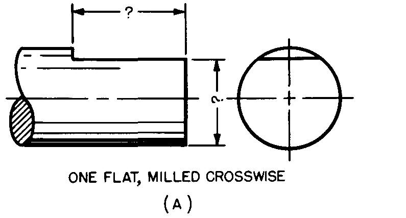
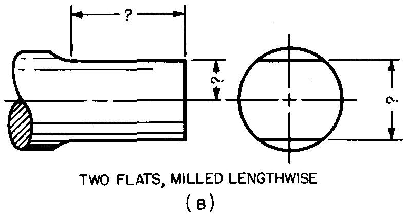
A flat is a surface which is produced by milling a portion of an external cylindrical surface. Flats are generally made to prevent the turning or slipping of pulleys, collars, and so on which are connected to shafts.
A set screw threaded into the pulley or collar pushes tightly against the flat, thus preventing the shaft from twisting in the hole. Flats are specified on drawings as shown in Fig. 12-62.
Fig. 12-62. Specification of flats
Keys and taper pins
Fasteners which are used to join and prevent rotation of two or more assembled machine parts are called keys and taper pins.
Generally, one of the parts is a shaft, while the other part may be a pulley, gear, wheel, cutter, cam, propeller, coupling, handwheel, or crank.
Figure 12-63 illustrates the difference between a keyseat and a keyway.
Fig. 12-63. A keyseat and a key way
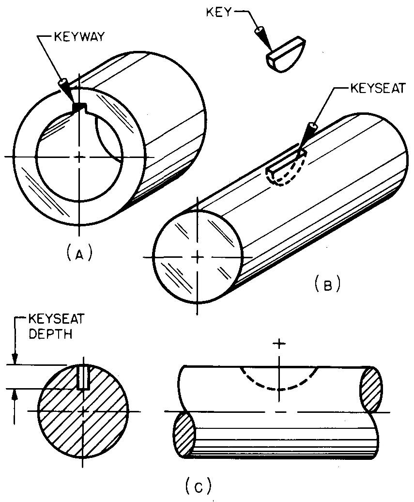
The keyseat (Fig. 12-63B) is a groove which is cut in the shaft.
The keyway (Fig. 12-63A) is a groove which is cut in the mating part. Thus, the key fits partly in the shaft and partly in the mating part.
The depth of the keyseat is always measured on the side, as shown in Fig. 12-63C.
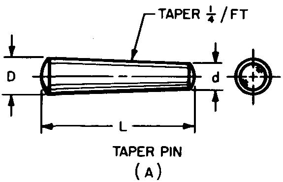
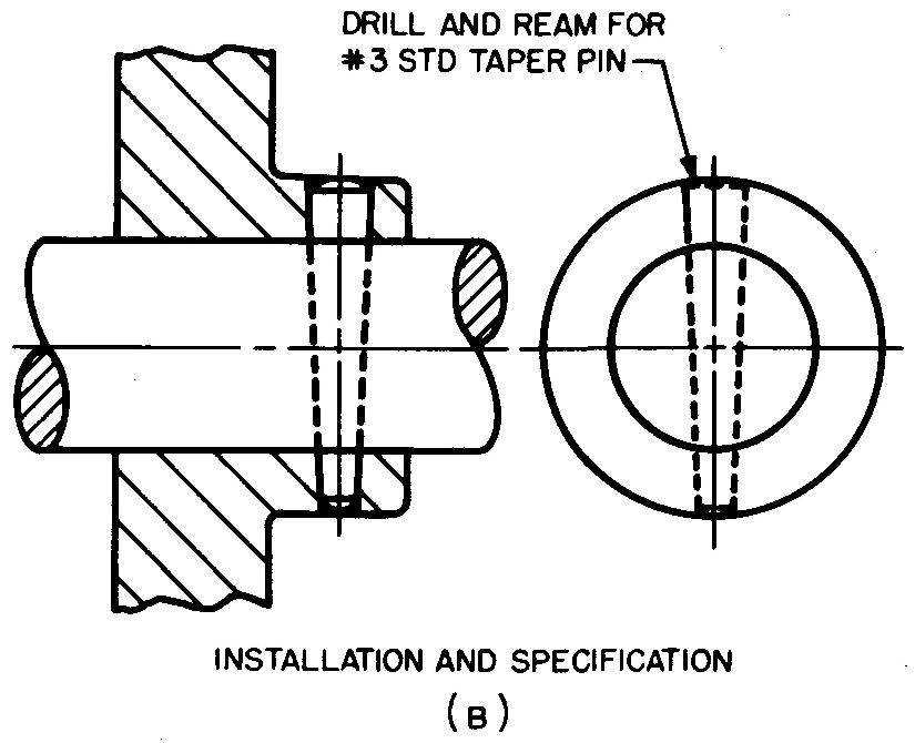
Figures 12-64 through 12-69 illustrate the more common types of keys and taper pins and show how to draw and specify these fasteners on a drawing. Tables 38, 39, and 48 through 52 list complete dimensions for keys and taper pins.
Fig. 12-64. The Woodruff key
KEY SIZE SELECTION - the key width (W) should be equal to approximately % of the shaft diameter. One half of the key is sunk into the shaft.
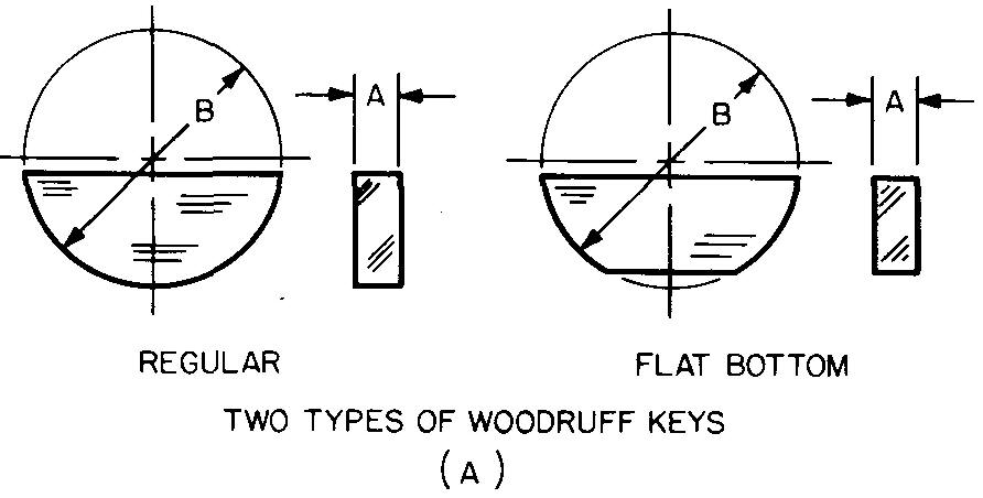
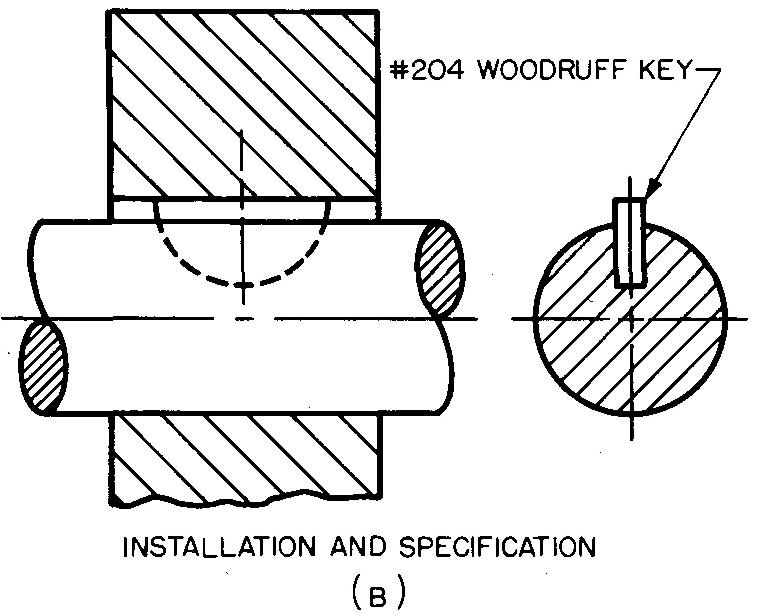
Fig. 12-65. The square key
KEY SIZE SELECTION - the key width (W) should be equal to approximately 14 of the shaft diameter. One half of the key is sunk into the shaft.
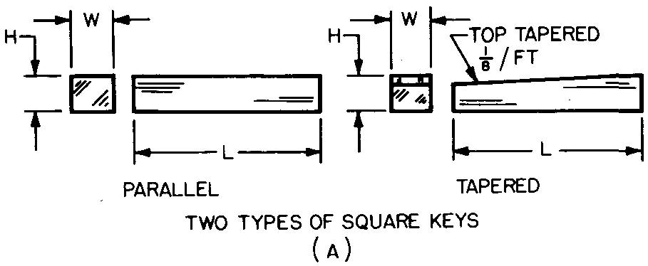
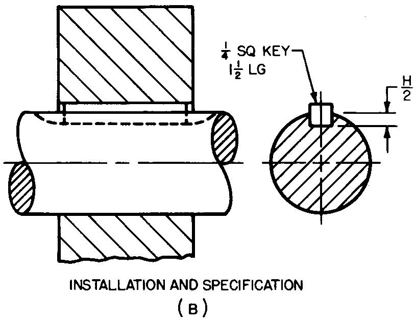
Fig. 12-66. The flat key
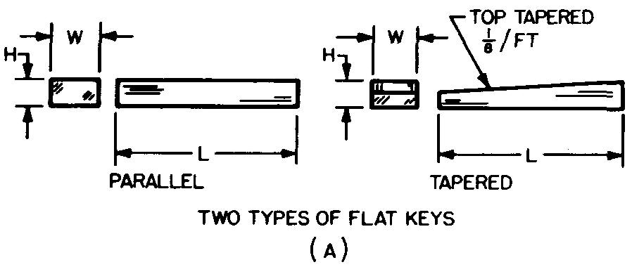
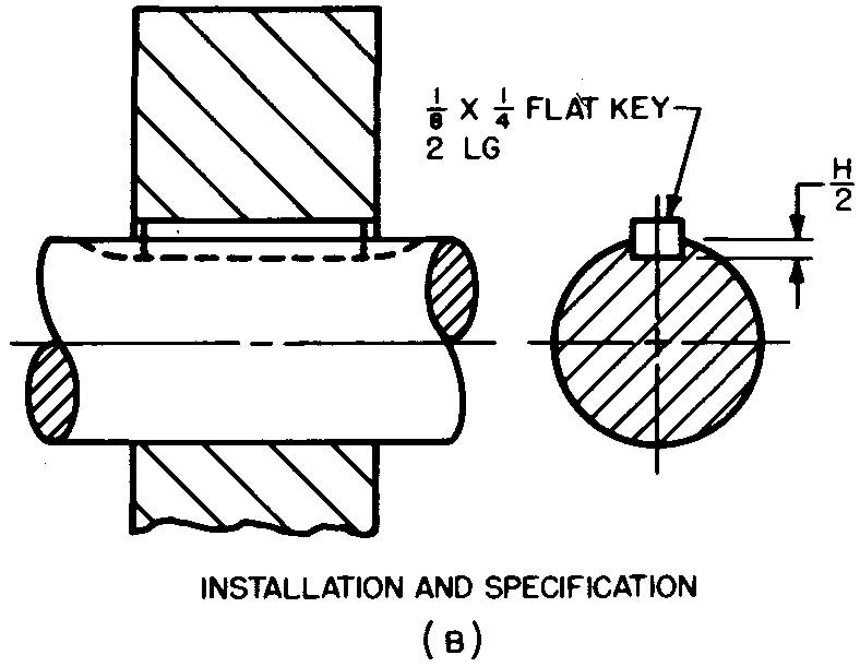
Fig. 12-67. The Pratt & Whitney key
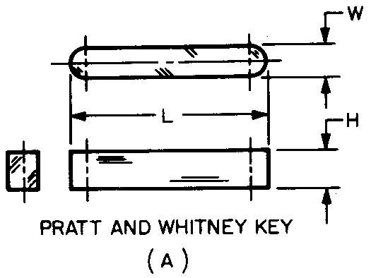
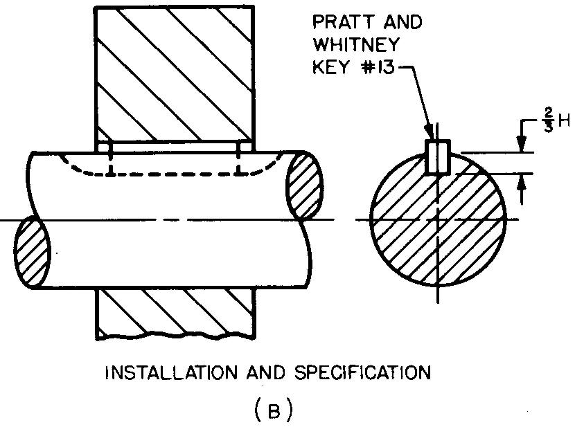
Fig. 12-68. The gib-head key
KEY SIZE SELECTION — the key is available in both the square or the flat, parallel or tapered. The L must be no less than 4W nor longer than 16W. Lengths are available every 2W.
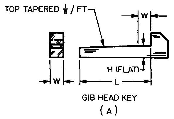
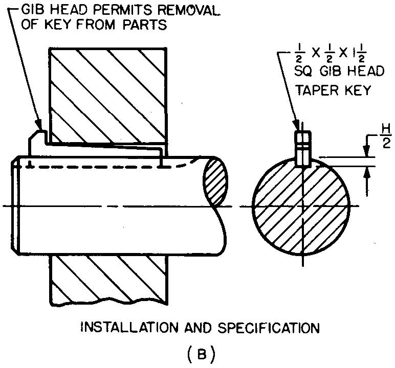
Fig. 12-69. A taper pin
PIN SIZE SELECTION - to find the small diameter of the pin (d), multiply the length (Z.) by 0.02083 and subtract the result from the large diameter (D). The value for D for several sizes of taper pins is found in Table 38.
Common terms
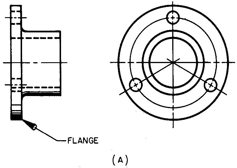
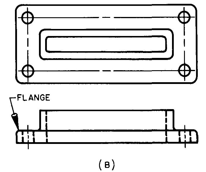
Flange
A projecting lip or edge of a part, usually intended to stiffen, strengthen, or fasten one part to another, is shown in Fig. 12-70.
Fig. 12-70. A flange
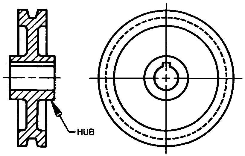
Hub
The solid metal around a center hole, usually on a wheel, gear, propeller, or pulley, is shown in Fig. 12-71.
Fig. 12-71. A hub
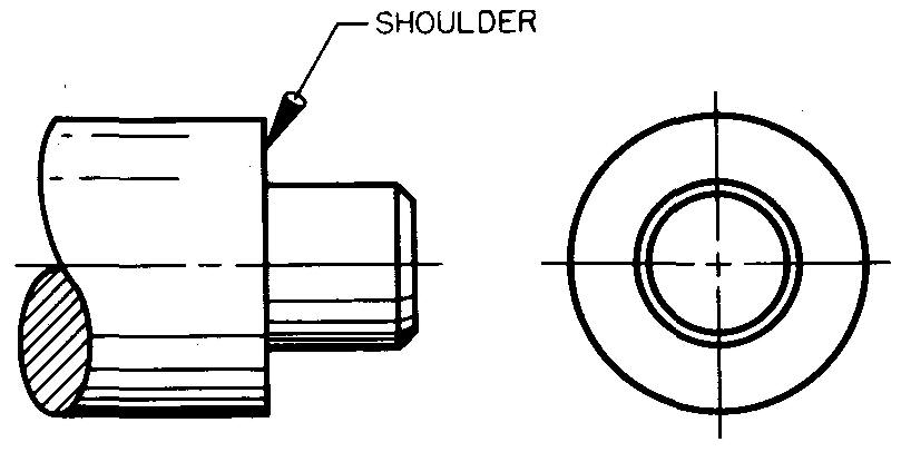
Shoulder
A flat surface on a shaft which is perpendicular to the axis. It is formed by the difference in two adjacent diameters. A shoulder is shown in Fig. 12-72.
Fig. 12-72. A shoulder
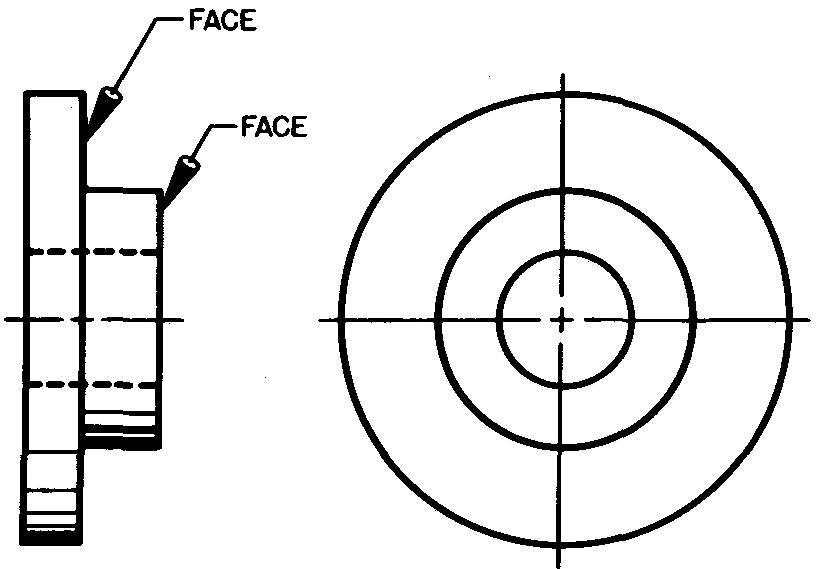
Face
A flat surface which is formed by machining or finishing a part on a lathe, shown in Fig. 12-73. A face is usually associated with circular parts, but it may also apply to a surface of a part of any shape.
Ffig. 12-73. A face
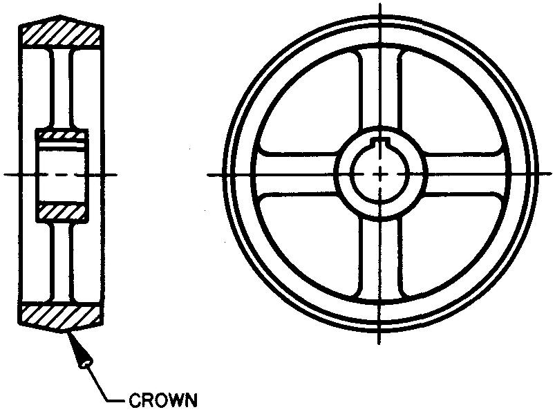
Crown
An angular or rounded surface commonly found on the cylindrical surface of pulleys or on the ends of round shafts or handles, shown in Fig. 12-74.
Fig. 12-74. A crown
Review questions (The answers are not given)
1. Drills used for most metals are ground to what angle?
2. If a drilled hole is shown extending entirely through a part, should the note specify the depth of the hole? Explain.
3. How do drilling and boring differ?
4. Describe the process of punching a hole.
5. For what purposes are countersunk holes made?
6. Explain what is meant by clearance drilling.
7. Sketch two views of a counterbored hole in a metal block.
8. What is the purpose of a spotfacing operation?
9. How do spotfacing and counterboring differ?
10. Why is it permissible to omit the depth of a spotfacing operation in the note?
11. Define external and internal threads.
12. What is meant by the term thread form?
13. Which thread form is used for the large majority of threaded fasteners in the United States?
14. Under what conditions are the Square and Acme thread forms used?
15. Give one important use of the Knuckle thread form.
16. Regardless of which method is used to produce an internal thread, what operation must be accomplished beforehand?
17. Explain the reasons for tap drilling.
18. What is the name of the tool used to produce an internal thread?
19. External threads are produced by one of two methods: cutting or rolling. Which method results in a better surface finish, increased strength, and greater accuracy? Explain.
20. Can a thread form drawn as schematic or simplified be identified by the way it is represented on a drawing? Explain.
21. What is meant by thread series?
22. What is meant by thread classes?
23. What is the tool called which is used to produce a reamed hole?
24. What is the purpose of reaming?
Refer to the indicated Appendix tables.
25. See Table 5.
a. Give the amount of tolerance
for a 15/16 diameter drilled hole.
b. For a 3/8 diameter reamed hole.
26. See Table 8.
a. Give the tap drill size for
a 1/2-20 UNC tapped hole.
b. Give the number of threads per inch for a 1/4
UNC thread.
c. Give the decimal equivalent size for a #10 thread.
27. See Table 9. Give the number of threads per inch for a 5/8 Acme thread.
28. See Table 12.
a. Give the decimal equivalent
size for a #65 diameter drill.
b. Give the decimal equivalent size for an F
diameter drill.
c. Give the drill size letter which is closest to 3/8
diameter.
29. See Table 13. Give a note specifying the clearance drill and the spotface diameter for a 1/2-inch regular semifinished hex bolt. (Allow 1/32 clearance for the bolt and specify a spotface diameter which will provide a head clearance to the closest 1/16 inch increment.)
30. See Table 14. Give a note specifying the clearance drill, counterbore diameter, and depth for a 5/16 inch socket-head cap screw. (Allow 1/32 clearance for the drill and spotface diameters. The top of the bolt head should be in line with the adjacent surface of the part in which it is to be installed.)
31. See Table 15. Give a note specifying the clearance drill and countersink for a 3/8 inch flat-head machine screw. (Allow 1/32 clearance for the screw and specify the countersink diameter to the closest 1/32 inch increment.)
