Conventional representation
Introduction
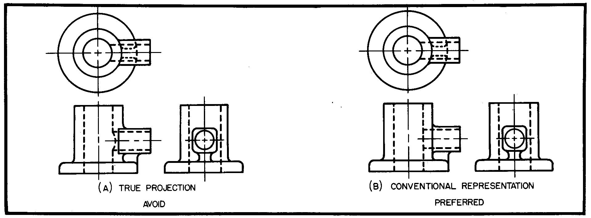
The usual or common method of drawing and specifying the various features of machine parts is called true projection. But, depending upon the shape of the part, some true projections are confusing and even misleading.
It is occasionally necessary for the draftsman to violate some of the principles of projection in an effort to make the views clearer to the shopman. Views of parts drawn in this manner are called conventional representations.
Besides providing views which are clearer to the reader, conventional representations often save drafting time, since the conventional views are usually simplified views.
In the examples to follow, the student should carefully examine and compare the views showing the part as it would look if projected exactly, or the true projections, with the conventional representations of the same part.
The illustrations to follow show some of the more common examples of conventional representations. Many companies have developed other conventional projections which apply principally to their own drafting requirements.
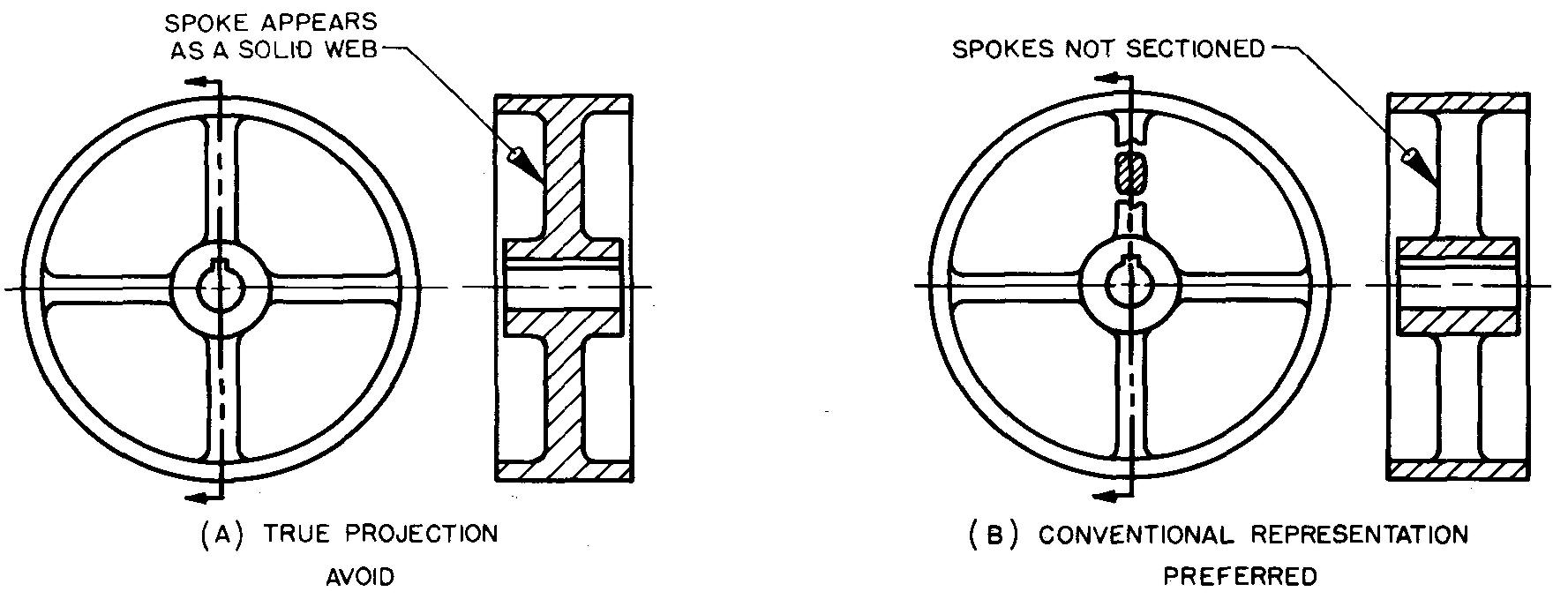
Spokes in section
In Fig. 5-1A, the sectional view is misleading, since the section lining on the spokes may make them appear to represent a solid web. Note the improvement in Fig. 5-IB, where the section lining is omitted on the spokes, even though the spokes are in the cutting plane.
Fig. 5-1. Spokes in section
Note also the revolved section which has been added to show the cross sectional shape of the spokes.
Figure 5-2A shows how confusing a true projection may be for some views. This confusion usually occurs when sectioning parts such as these which have an odd number of equally spaced spokes or other similar features.
Fig. 5-2. Spokes in section
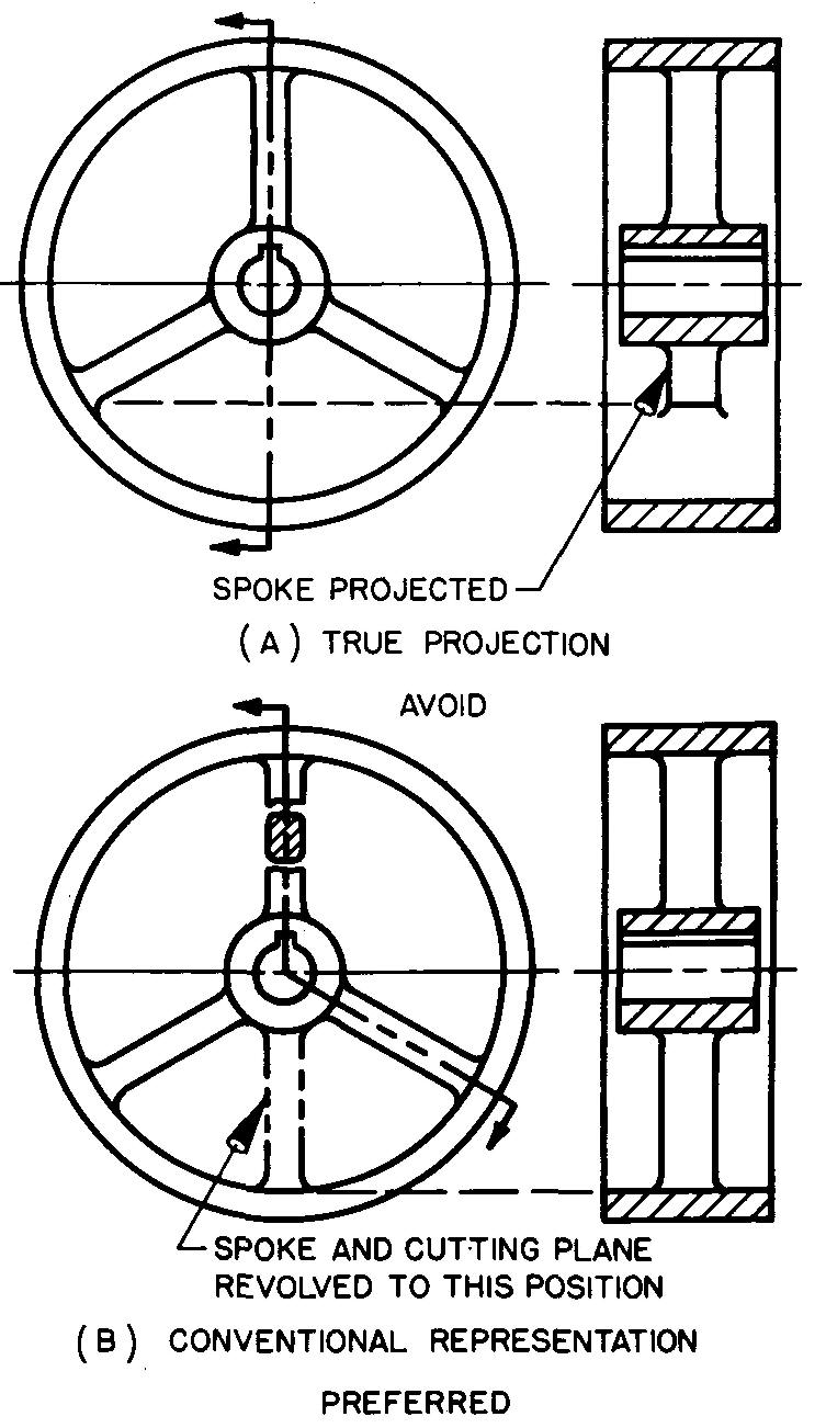
The part shown in Fig. 5-2A has three spokes which are equally spaced.
The upper spoke is the only one of the three spokes which is cut by the cutting plane. In a true projection, only the particular spoke cut can be shown in the sectional view.
The confusion, therefore, is due to the way in which the other spokes must be represented. To make the sectional view clearer to the reader, spokes which do not lie in the cutting plane are revolved as if they actually were in the plane.
Note the obvious advantage of the conventional representation in Fig. 5-2B over the true projection in Fig. 5-2A.
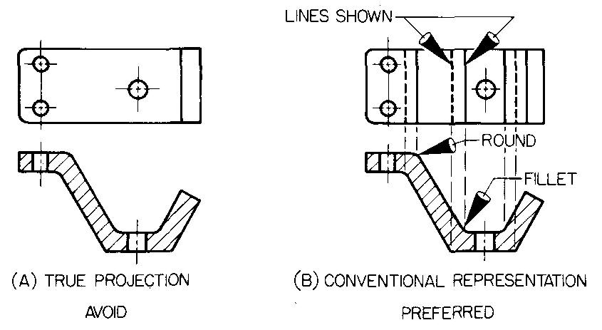
Ribs and webs in section
Note how much more evident the ribs are in part 1 of Fig. 5-3B than in Fig. 5-3A.
Fig. 5-3. Ribs in section
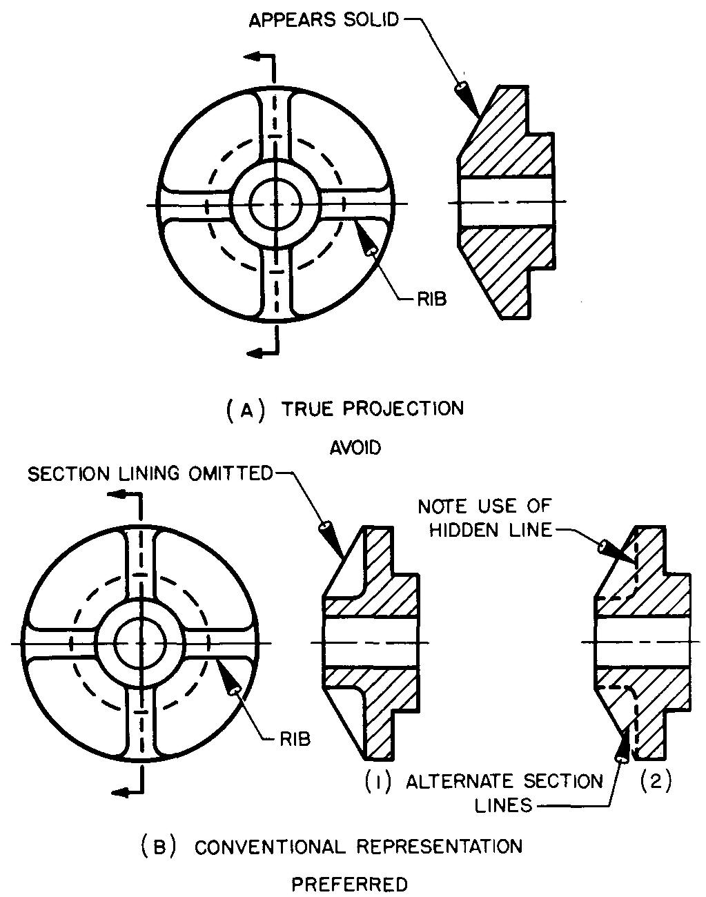
This advantage comes from the convention which omits the section lining from the ribs.
Another acceptable method is to draw only the alternate section lines shown in part 2 of Fig. 5-3B. This method is not as frequently used as the first convention.
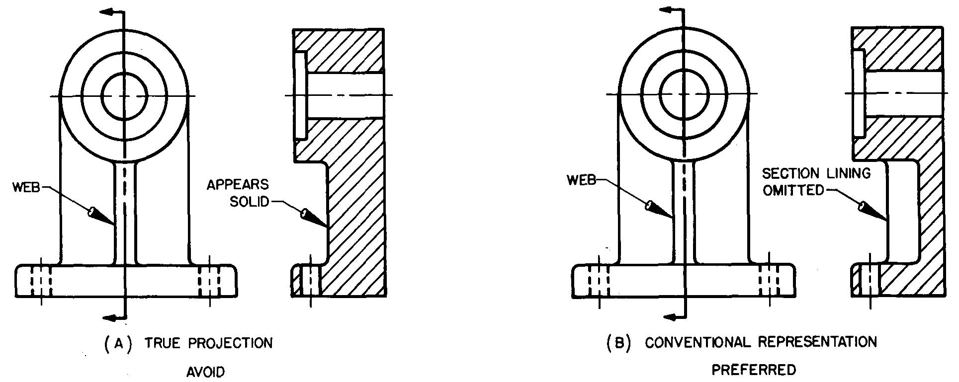
Figure 5-4 shows how to section parts which have a web.
Fig. 5-4. Webs in section
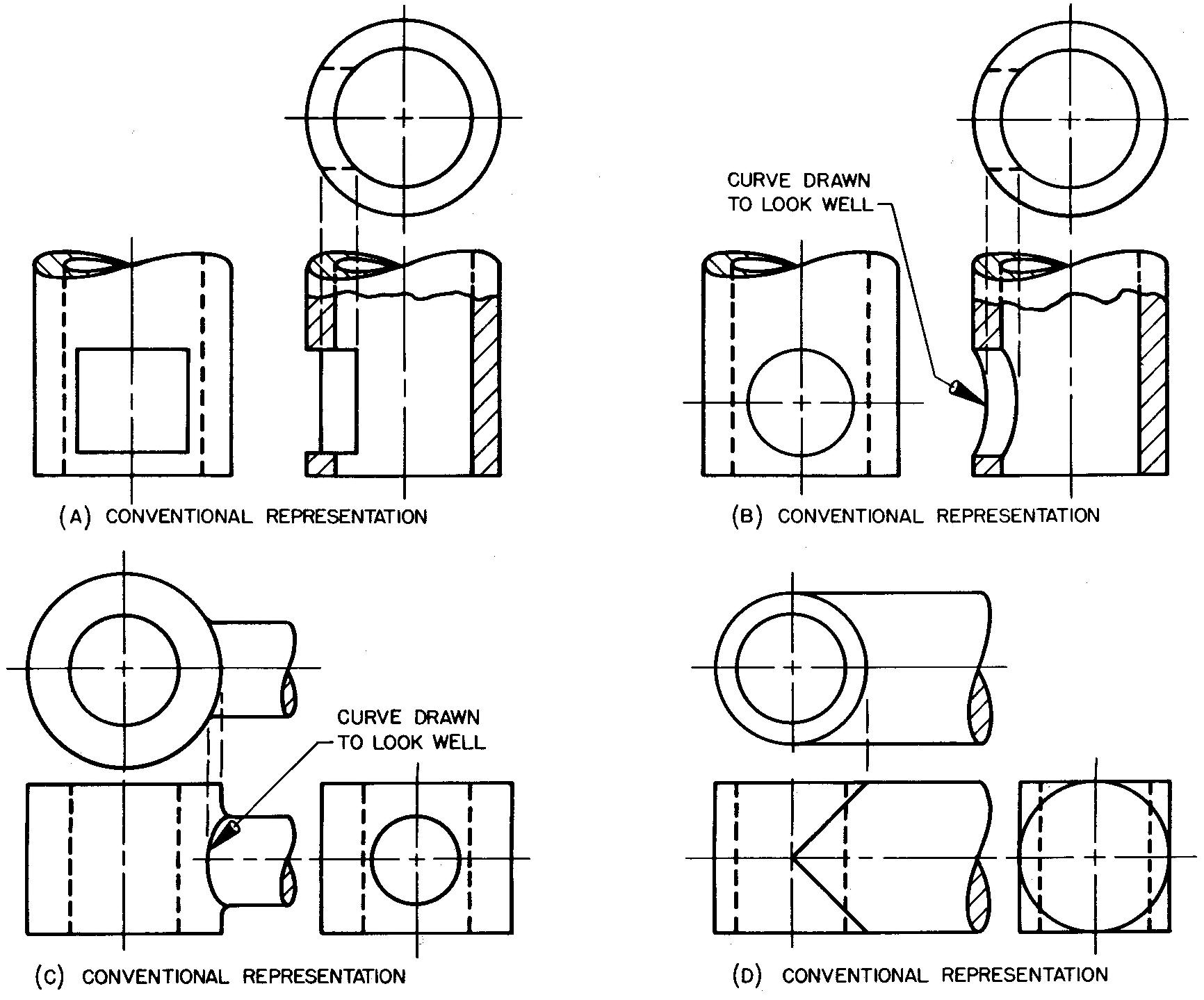
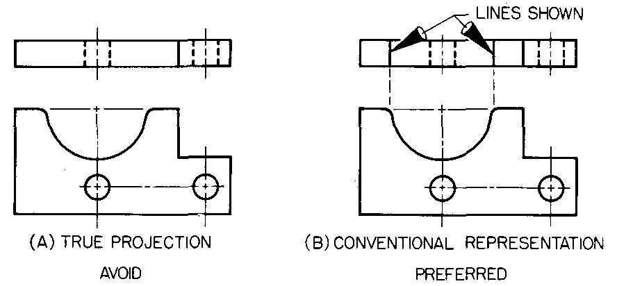
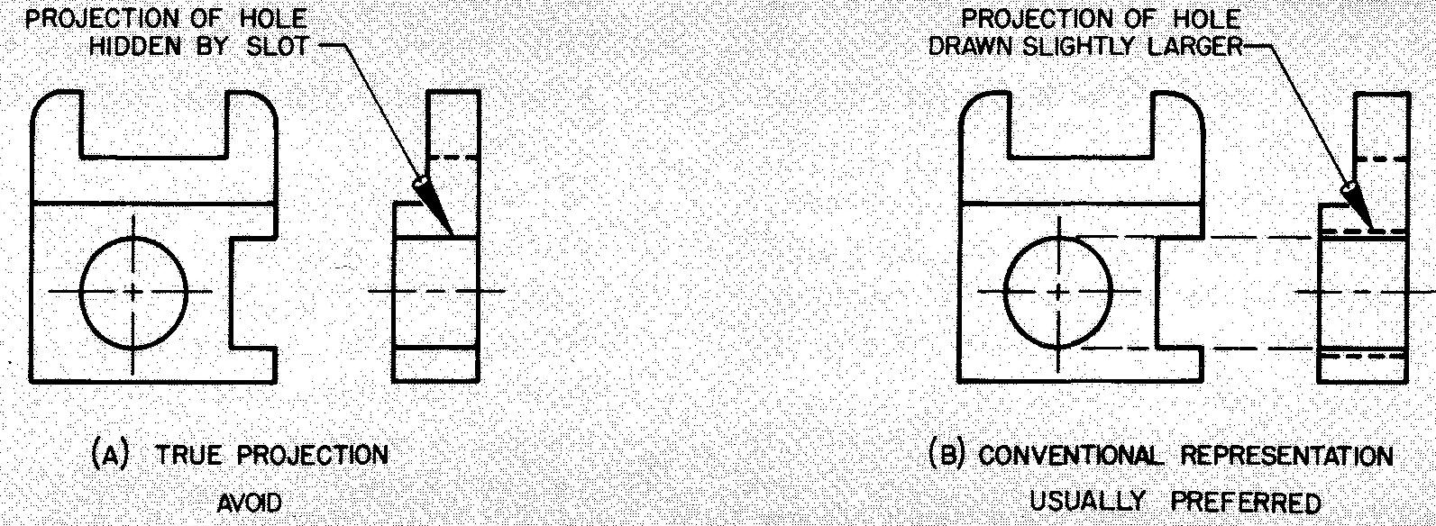
Holes in section
The small hole has been omitted in the true projection sectional view in Fig. 5-5A. Figure 5-5B shows how the cutting plane may be aligned (or bent) so as to pass through the hole.
Fig. 5-5. Holes in section
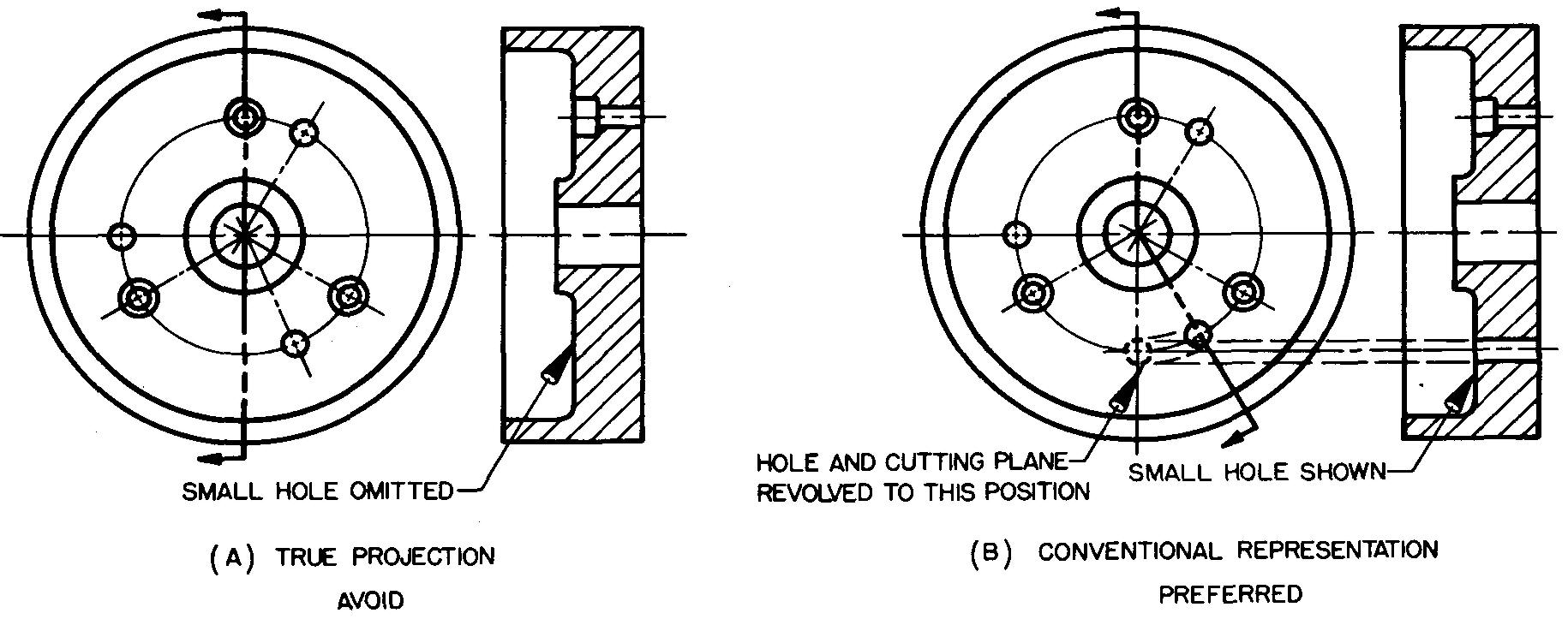
The cutting plane and hole are then revolved as if they were in the original plane, producing a conventional representation which is of greater use in the shop than a true representation would be.
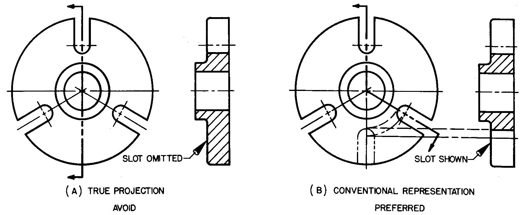
Slots in section
Note how the sectional view in Fig. 5-6A gives the false impression that only the upper slot is required. As with holes in section, the cutting plane and slot should be revolved as if they were in the original plane, as in the conventional representation (Fig. 5-6B).
Fig. 5-6. Slots in section
Lugs in section
A comparison of Fig. 5-7A and B shows this principle applied to lugs in section.
Fig. 5-7. Lugs in section
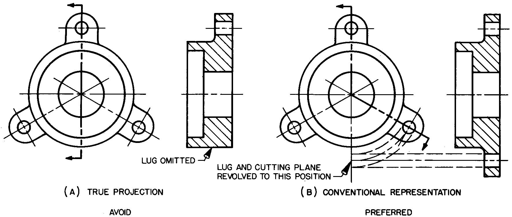
Similarly to spokes, holes, and slots in section, the cutting plane is aligned (or bent) so as to pass through the lug as shown in Fig. 5-7B. Since the cutting plane passed through the lug crosswise, the lugs are sectioned.
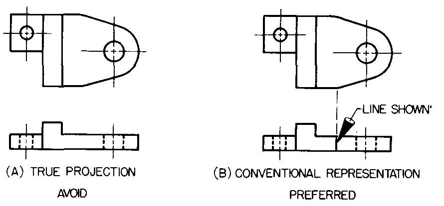
In Fig. 5-8A, the cutting plane did not pass through the lug crosswise.
Fig. 5-8. Lugs in section
Therefore in the preferred representation, (Fig. 5-8B), the lug is not sectioned. By omitting the section lining, the draftsman can prevent a false impression that the lug is a circular flange or rim connected to the hub.
The sectional view in Fig. 5-8B clearly shows that this is not true.
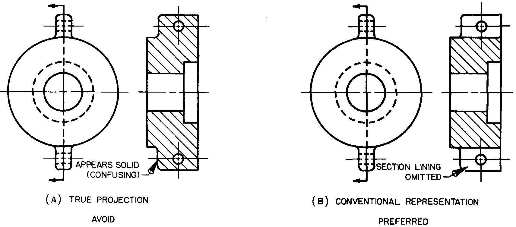
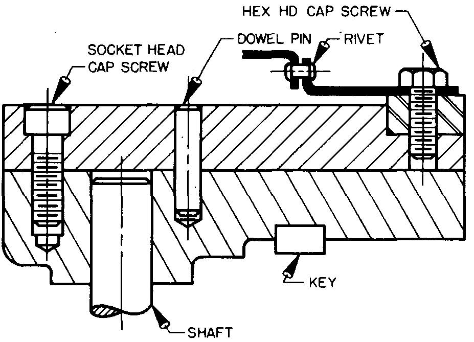
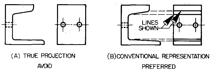
Sectioning with standard parts
When the cutting plane cuts shafts, bolts, nuts, rods, rivets, washers, keys, pins, and other standard parts, section lining is omitted, as shown in Fig. 5-9.
Fig. 5-9. Sectioning views with standard parts
Intersections
When the exact line of intersection formed by two surfaces which meet is of no particular importance, the line of intersection may be simplified. Figures 5-10 through 5-13 Illustrate this principle.
Fig. 5-10. Small intersections: internal
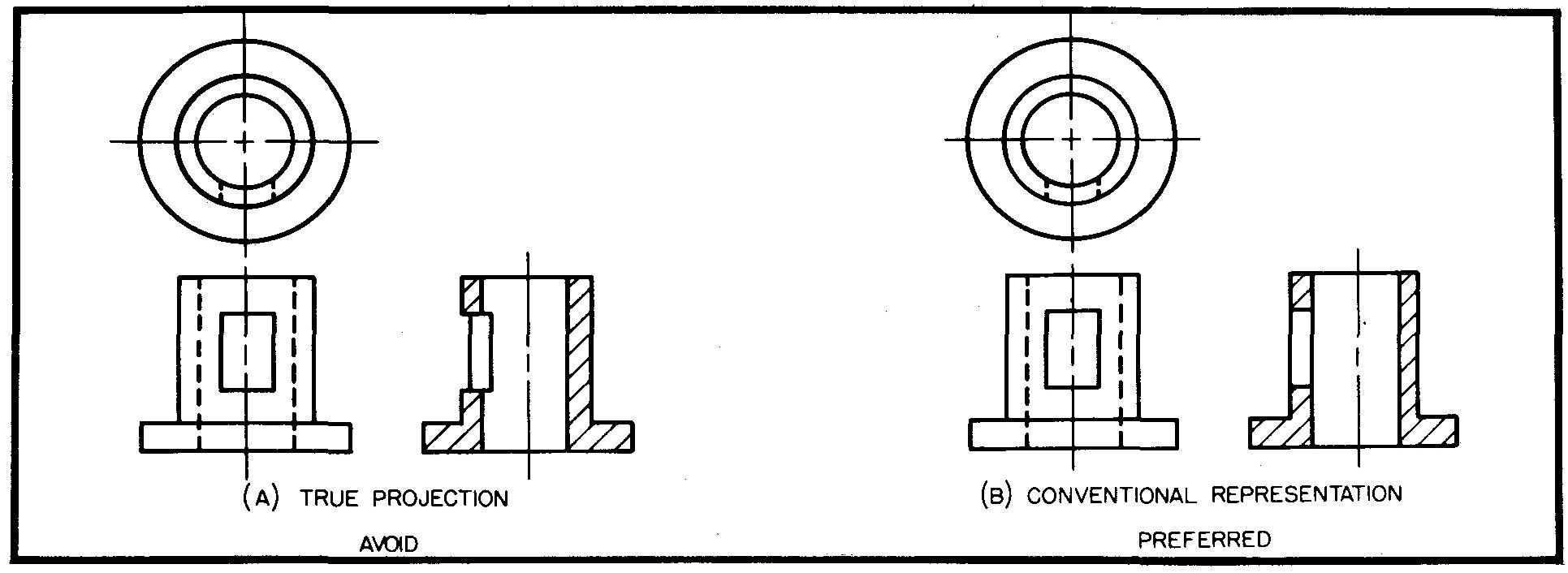
Fig. 5-11. Small intersections: internal
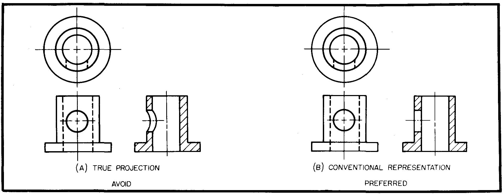
Fig. 5-12. Small intersections: external
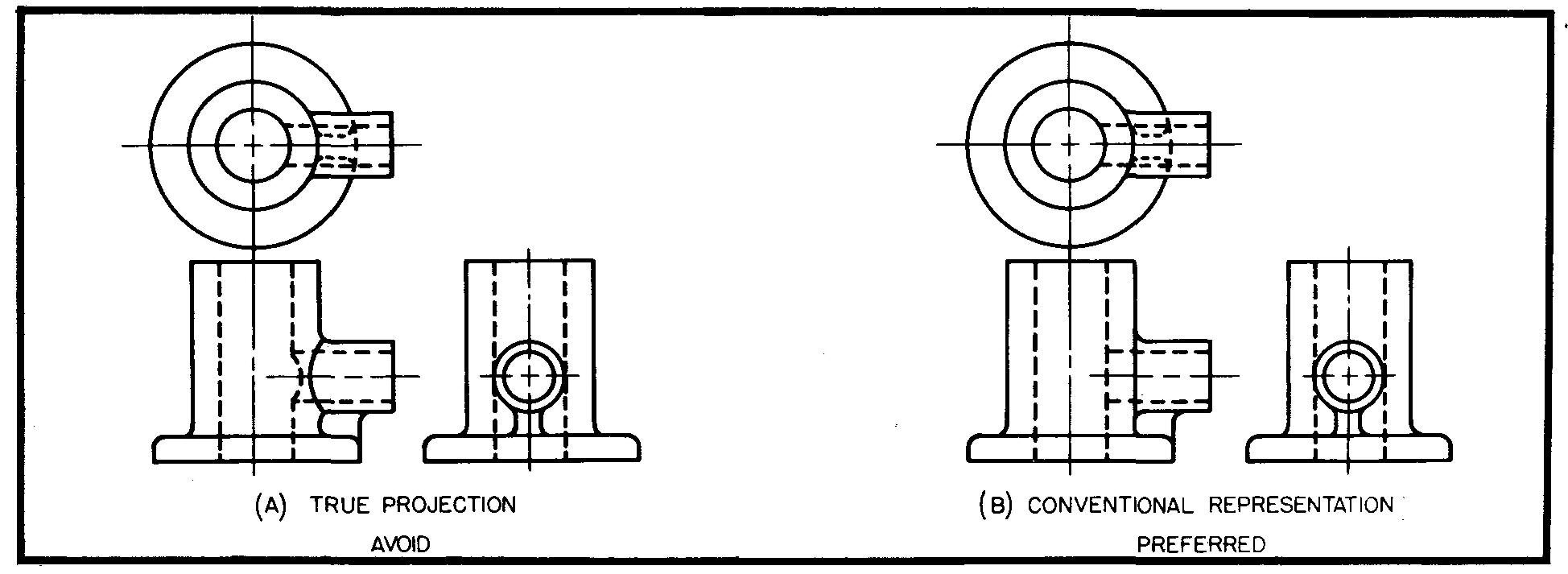
Fig. 5-13. Small intersections: external
Selected points on the lines of intersection for some large parts may be projected to the next view as a guide through which the curves of the line of intersection may be accurately drawn.
On the other hand, the curves may be better represented by drawing them as an approximation of the actual outline. These ways of treating the lines of intersection are illustrated in Fig. 5-14.
Fig. 5-14. Large intersections
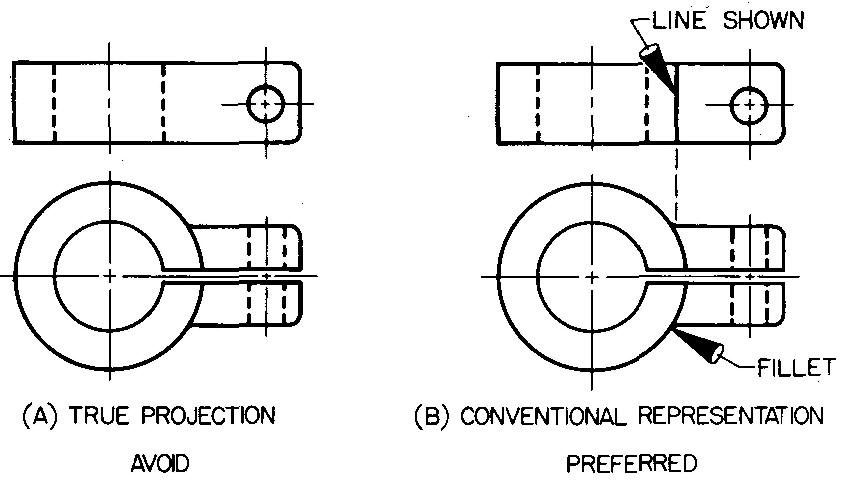
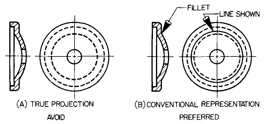
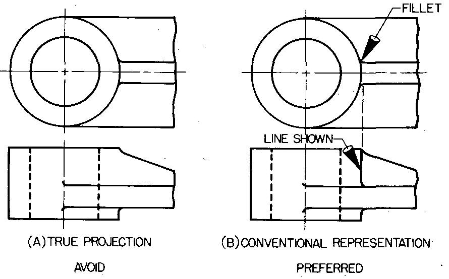
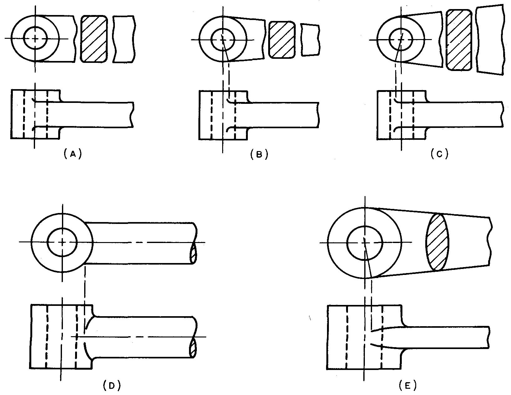
Fillets, rounds, and runouts
Parts which are formed by casting or by forging are designed with rounded inside and outside corners since sharp corners are difficult to forge or to cast since they create structural defects.
Rounded corners make the part safer to handle and they usually improve the appearance of the part. Inside corners are rounded for greater strength because of the possibility of parts breaking at sharp corners.
Curves on outside corners are called rounds. Curves on inside corners are called fillets. Runouts are formed when ribs, webs, spokes, and so on run or blend into other surfaces, as shown in Fig. 5-15.
Fig. 5-15. Fillets, rounds, and runouts
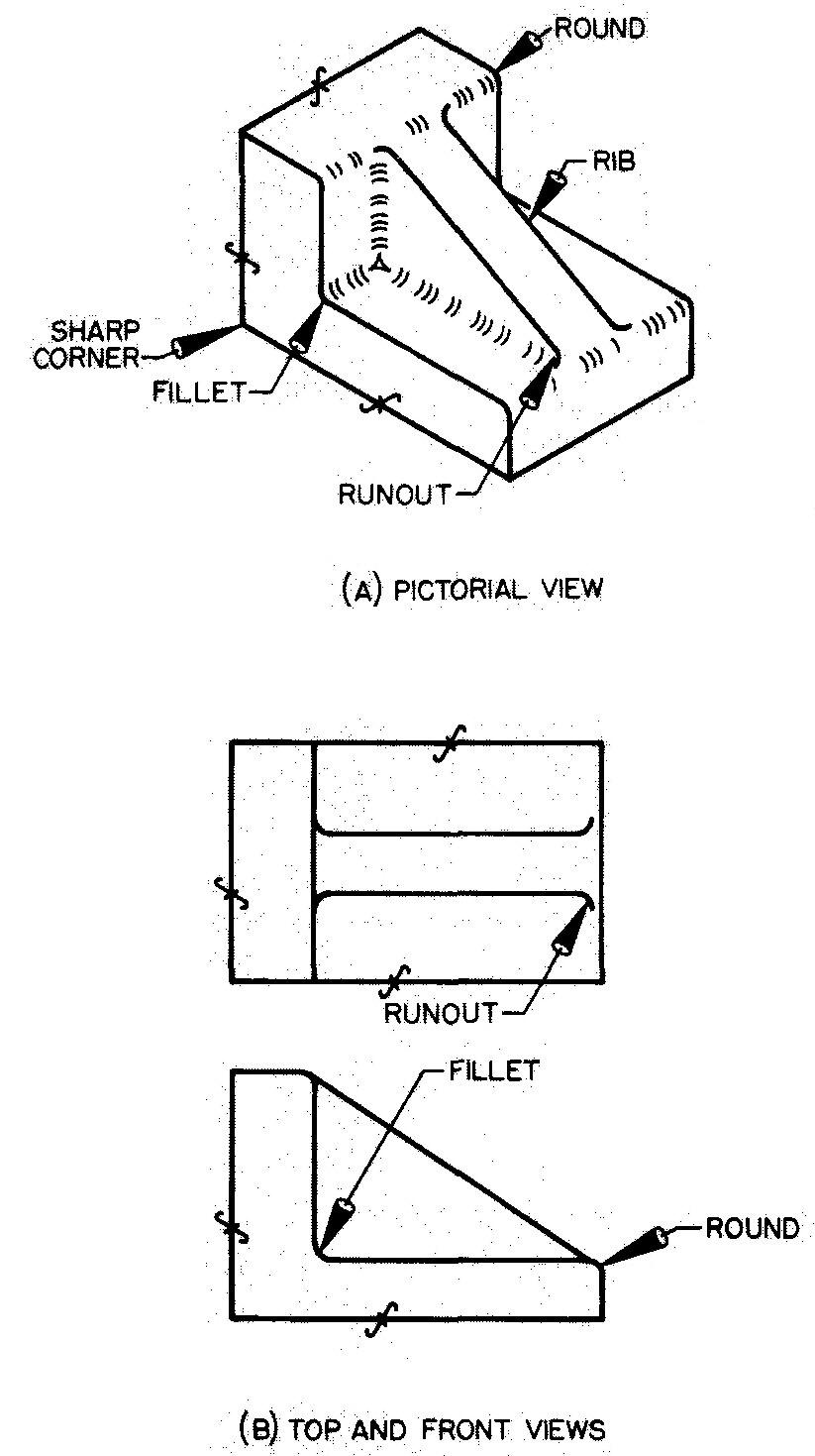
Dimensions are usually omitted for small fillets and rounds. The size is usually specified in a general note: All fillets and rounds to be 1/8-in. radius unless otherwise specified. Large radii (over 3/8 inch) are dimensioned.
Curves for small fillets, rounds, and runouts are usually drawn freehand. If the draftsman desires, these curves may be drawn with a template or a compass.
A drawing of a machine part shows how the part will appear after it has been completely made.
In effect, the part is ready for use as drawn. Thus a cast or forged part may be drawn with any number of sharp corners, depending upon which of the surfaces are to be machined.
Rounded corners become sharp corners on the part when one or both of the two intersecting surfaces have been finished (or machined) as shown in Fig. 5-15B.
Draftsmen should be alert to show sharp corners when representing views with a finished surface and rounded corners where no machining is necessary.
In Figs. 5-16 through 5-23, note examples of conventions which apply to parts with fillets, rounds, and runouts.
| Fig. 5-16. Projection of fillets | Fig. 5-17. Projection of fillets |
 |
 |
| Fig. 5-18. Projection of rounds | Fig. 5-19. Projection of rounds |
 |
 |
| Fig. 5-20. Projection of fillets | Fig. 5-21. Projection of fillets |
 |
 |
| Fig. 5-22. Projection of fillets and rounds | Fig. 5-23. Projection of runouts |
 |
 |
When the sizes of fillets and rounds vary often on one drawing, each radius should be dimensioned separately. Otherwise only the occasional fillets and rounds that vary from the indicated size should be dimensioned.
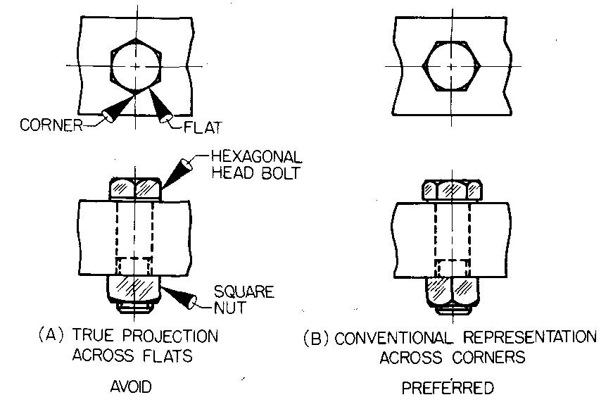
Bolt heads and nuts
Bolt heads and nuts (either square or hexagonal) are generally represented by drawing them across corners. Views showing them across flats are often confusing because they fail to show the largest size, which is the distance across corners.
Figure 5-24 compares the two views. The flats on nuts and bolt heads are represented by the sides where the wrench engages.
Fig. 5-24. Projection of bolt heads and nuts
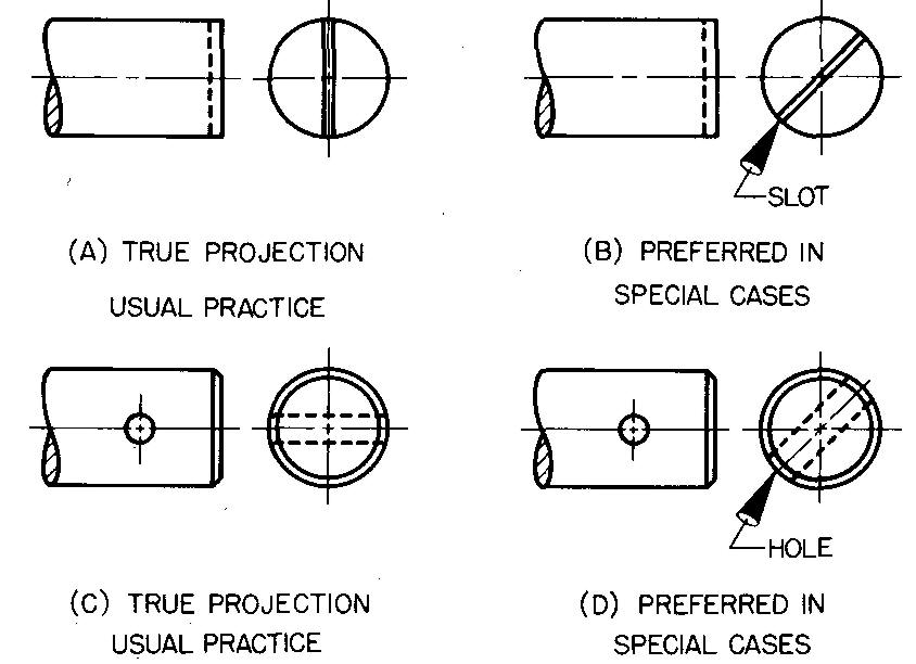
Slots and pin holes
The screwdriver slot is always shown in the circular view for bolts and screwheads. Figure 5-25 compares the true projection and the conventional representation for showing these slots.
Fig. 5-25. Projection of a screwdriver slot
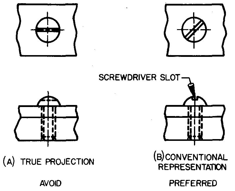
The slot is better drawn at an angle of 45°, as shown in Fig. 5-25B. This convention applies also to the drawing of slots and pinholes, as shown in Fig. 5-26.
Fig. 5-26. Projection of slots and pinholes
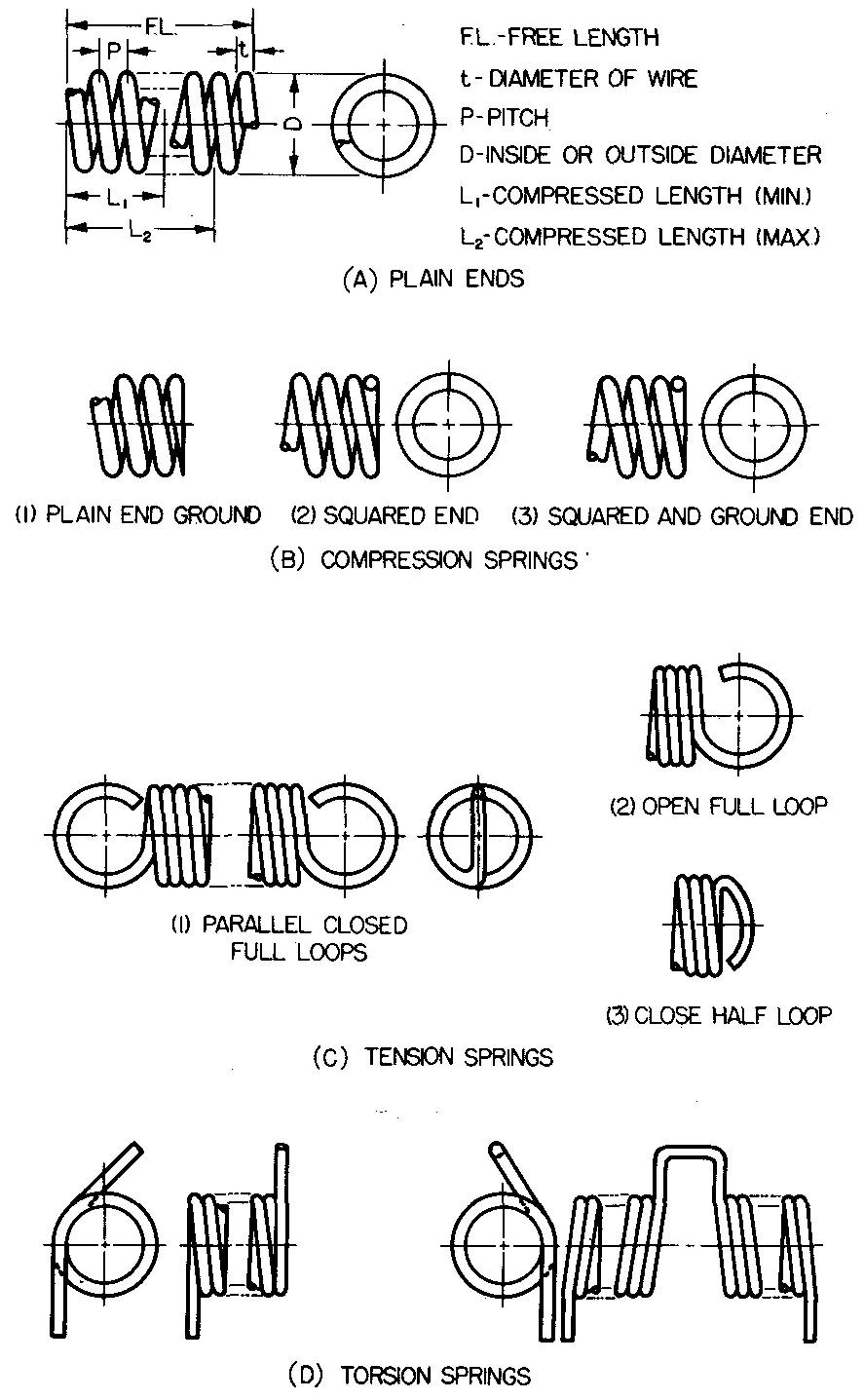
Springs
Specification
Some of the more common kinds of springs are shown in Fig. 5-27.
fig. 5-27. common kinds of springs (ASA Z 14.1-1946)
Draftsmen in many companies use standard drawing sheets when drawing springs. These consist of a drawing sheet (usually 8-1/2 by 11 inches) upon which is printed a table listing the data necessary for the manufacture of the desired spring.
The draftsman, in this case, merely fills in the necessary information.
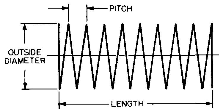
This information usually includes: the kind of spring (compression, tension, or torsion); the free length; the outside or inside diameters; the wire size and shape; the number of coils (or pitch of the spring); the material from which the spring is made; and the style of the ends.
Representation
Springs are represented on a drawing by using either the semi conventional or single-line conventional method. Figure 5-28, steps 1 through 4, illustrates the semi conventional method for drawing a spring.
Fig. 5-28. Semi conventional representation of springs
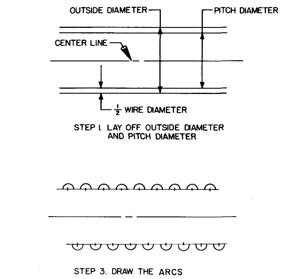
The method is similar to the method by which the detailed representation of a screw thread is drawn (see Sec. 12 Drawing detailed thread representations).
Figure 5-29 illustrates a spring drawn as a single-line convention.
Fig. 5-29. Single-line representation of springs
Long springs
Some springs are unusually long. In these cases, drawing each coil of the entire spring is often unnecessary. Time and effort may be saved by drawing two or three coils at either end and by connecting them with phantom lines, as shown in Fig. 5-30.
Fig. 5-30. Representing long springs
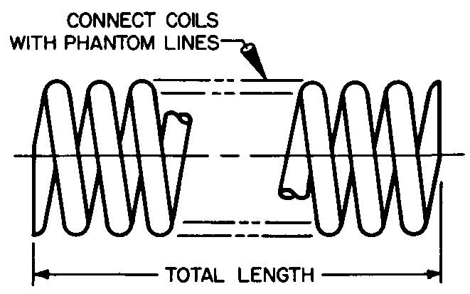
This practice saves the draftsman much time that would be spent in repetitious symbol drawing.
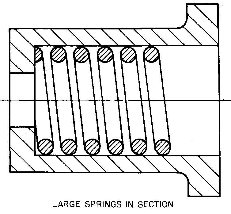
Springs in section
Small springs in section are represented by blacking in the wire shapes, as shown in Fig. 5-31. Larger springs in section are represented by the usual section lines, as illustrated in Fig. 5-32.
Fig. 5-31. Representing small springs in section
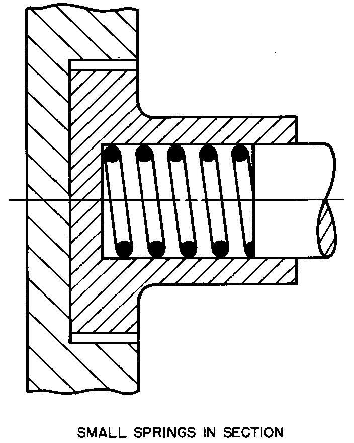
Fig. 5-32. Representing large springs in section
Intentional violations of projection
Lines may occasionally be moved out of true position to make a certain feature of a view as evident as possible, as shown in the comparison of views in Fig. 5-33.
Fig. 5-33. Intentional violations of projection
The dotted lines representing the sides of the hole in the right-side view, Fig. 5-33B, have been drawn slightly farther apart than the true dimensions to prevent the hole from being confused with the sides of the slot.
This method is reserved for special cases when it is necessary to show on a view a particular feature which might not be otherwise understood.
Breaks
It is usually unnecessary to draw a view of the entire length of a long part such as a bar or pipe which has a uniform cross section. The shape of the cross section may be represented as in Fig. 5-34.
Fig. 5-34. Representing breaks
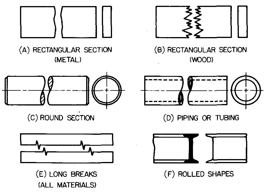
A dimension should be given on a detail drawing specifying the exact length. Breaks are generally drawn freehand. An irregular curve, template, or compass may be used if desired to draw breaks for round parts.
One-view drawings
When it is evident the part is completely symmetrical and basically composed of cylinders, it is permissible to draw only the profile view or the view which shows the outline of the part.
One-view drawings save drafting time. They are particularly useful for drawing parts in limited spaces on the drawing sheet. In Fig. 5-35A, all dimensions have been placed on the profile view. In Fig. 5-35B, the circular view has been omitted entirely.
Fig. 5-35. one-view drawings
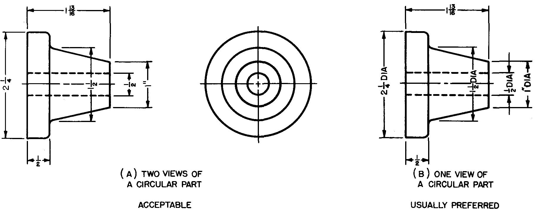
The symbol DIA has been added to the diameter dimensions of the part. Some companies require a minimum of two views of all parts; such company restrictions do not permit the use of one-view drawings.
Half views
Half views of symmetrical parts are often drawn to save drafting time. They may also be drawn when the available space on the sheet is limited. Special caution must be used when drawing half views.
In Fig. 5-36A, the front view is not sectioned; therefore the front half of the top view should be drawn.
Fig. 5-36. Half views
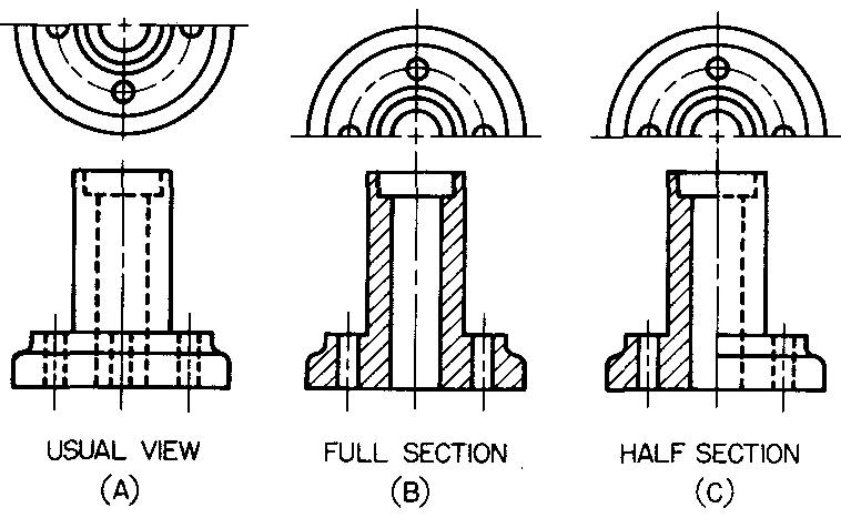
If the front view is to be sectioned, as in Fig. 5-36B, the rear half of the top view should be drawn. Figure 5-36C shows the front view as a half section. Hidden lines are drawn for dimensioning purposes. Some companies do not permit the use of half views.
Review questions (The answers are not given)
1. Describe what is meant by conventional representation.
2. What is meant by a true projection!
3. Explain why the spoke representation in Fig. 5-2 is said to be misleading.
4. Why is section lining omitted on ribs and webs in sectional views?
5. The slot in Fig. 5-6A is misleading. Explain.
6. When the cutting plane passes through lugs crossways, how are the lugs drawn?
7. What is the rule applying to section lining for standard parts?
8. Explain what is meant by a simplified intersection. Why is this method used on views of some machine parts?
9. Make a freehand sketch of a simple machine part with fillets, rounds, and runouts. Identify each.
10. How may a machined surface on a casting or a forging be identified on a drawing?
11. Why are views of bolt heads and nuts which have been drawn across flats often confusing?
12. What are the two methods used to represent a spring on a drawing?
13. How may the drawing time be reduced when drawing a long spring?
14. Make a sketch showing how springs are shown in section.
15. Describe what is meant by a break on a view of a part. Sketch a shaft with a break at one end.
16. Under what conditions may a one-view drawing be made of a part?
17. What is the advantage of drawing half views of parts?
Problems: principles of sectional views and principles of conventional representation
Using 8-1/2 by 11 inch graph paper or unruled paper prepare two- or three-view freehand technical sketches of the following problems.
Sketch the sectional views as indicated. Show the cutting plane, using identification letters where appropriate. Read the problem statements
carefully since certain features of the parts have been intentionally omitted on the illustrations. Estimate all omitted sizes. Space the views far enough apart to allow room for required dimensions and notes.
These will be applied to the views after you have studied section 6 and 7. Keep your sketches for this purpose.
group 1 full sections
problem 5-1 See Problem 13-7. (Omit flat.)
problem 5-2 See Problem 14-1.
problem 5-3 See Problem 15-24. (CP along center line of holes A and C.)
problem 5-4 See Problem 16-7.
problem 5-5 See Problem 17-9, Detail 4. (CP along center line of two adjacent plugs.)
problem 5-6 See Problem 17-11. (Base.)
problem 5-7 See Problem 17-14, Detail LA 225. (CP along long center line.)
problem 5-8 See Problem 17-19, Detail 2.
group 2 half sections
problem 5-9 See Problem 13-9.
problem 5-10 See Problem 13-14. (Refer to Figs. 12-35 and 12-36.)
problem 5-11 See Problem 14-2. (Refer to Figs. 12-35 and 12-36.)
problem 5-12 See Problem 14-9.
problem 5-13 See problem 14-22.
problem 5-14 See Problem 14-27.
problem 5-15 See Problem 15-4.
problem 5-16 See Problem 15-7.
problem 5-17 See Problem 16-9.
group 3 conventional representations for sectional views
problem 5-18 See Problem 13-17. (CP through slot and holes C and D.) This problem was previously assigned in section 3 (see Problem 3-3).
problem 5-19 See Problem 13-22. (CP through center line of tie rod holes and hole A.) This problem was previously assigned in section 3 (see Problem 3-5).
problem 5-20 See Problem 14-19. (Refer to Figs. 12-35 and 12-36.)
problem 5-21 See Problem 14-21.
problem 5-22 See Problem 14-34.
group 4 offset sections
problem 5-23 See Problem 14-46. (CP along center line of holes A, B, and A.)
problem 5-24 See Problem 14-47. (CP lengthwise along center line of holes A, B, C, and A.)
problem 5-25 See Problem 15-25. (CP lengthwise along center line of holes T, R, and S.)
group 5 removed sections
Prepare a sketch of the removed
sectional views only. Do not sketch the usual orthographic views of the machine
parts.
problem 5-26 See Problem 13-5. (Show octagonal shape.)
problem 5-27 See Problem 13-11. (Show shape across OD through slot.) This problem was previously assigned in section 3 (see Problem 3-27). Using the sketch made for Problem 3-27, add the removed sectional view.
problem 5-28 See Problem 13-24. (Show shape through holes C, D, and E.) This problem was previously assigned in section 3 (see Problem 3-28). Using the sketch made for Problem 3-28, add the removed sectional view.
problem 5-29 See Problem 14-24. problem 5-30 See Problem 15-21.
problem 5-31 See Problem 15-42. (Show shape through holes B.)
group 6 revolved sections
problem 5-32 See Problem 13-8. (Show circular shape.) This problem was previously assigned in section 3 (see Problem 3-14). Using the sketch made for Problem 3-14, add the required revolved sectional view.
problem 5-33 See Problem 14-32.
problem 5-34 See Problem 17-7. (Show shape through jaw side.)
group 7 broken-out sections
problem 5-35 See Problem 13-24. (Show shape through holes C, D, and E.) This problem was previously assigned in section 3 (see Problem 3-28). It was also assigned for Problem 5-28. Because of the special requirements for this problem, prepare a new freehand sketch.
problem 5-36 See Problem 15-8. (Show shape through hole A and square hole.)

![]()