Drafting mathematics Part 1
See Also Drafting mathematics Part 2
Introduction
Since the beginning of time man has always been interested in measuring the world around him, but man's skill in measurement has often varied during his long history.
In the days of the cave man, for instance, all measurements were made by simply stretching out one's arms or by comparing a certain distance to the length of one's foot or hand.
Measurements of the same distances naturally varied with the size of the man. While this form of measurement suited the needs of man at that time, it was inaccurate.
One of the earliest recorded standard measures was developed by the civilization of people living along the Nile. This early standard measure was called the cubit. Records of the cubit have been found dating back to 6000 B.C.
This cubit was the distance from the bent forearm at the point of the elbow to the tip of the finger on the outstretched hand. It amounted to approximately 18 inches.
Two thousand years after the first record of the cubit, it was fixed at exactly 18.24 inches.
The span was used for distances less than a cubit. This distance equalled the measurement between the tip of the thumb and the little finger of the outstretched hand. It was equal to 9 inches, or half a cubit.
A study of the dimensions of
the Pyramids shows that all their measurements are in multiples or in fractions
of the cubit.
Modern industry requires infinitely more accurate dimensions
than those used to build the Pyramids.
Most of the things we use in our daily living could not be produced economically without the use of precise measurement. The study of measurement has been greatly advanced since the building of the Pyramids.
It is now possible to measure
accurately to a millionth of an inch.
Drawings for machine parts must be
carefully dimensioned. Working out the values for dimensions accounts for a
surprising amount of a machine draftsman's time.
Most of the mathematics he uses is no more complicated than the orderly use of reasonably simple arithmetic processes. This mathematics is largely a matter of adding, multiplying, subtracting, and dividing and of squaring and finding the square roots of numbers.
The advanced mathematics required by modern industry is used by specially trained design and development engineers. Some of their typical problems include calculating the stress, the forces, the pressures, and the speed of moving parts for a product.
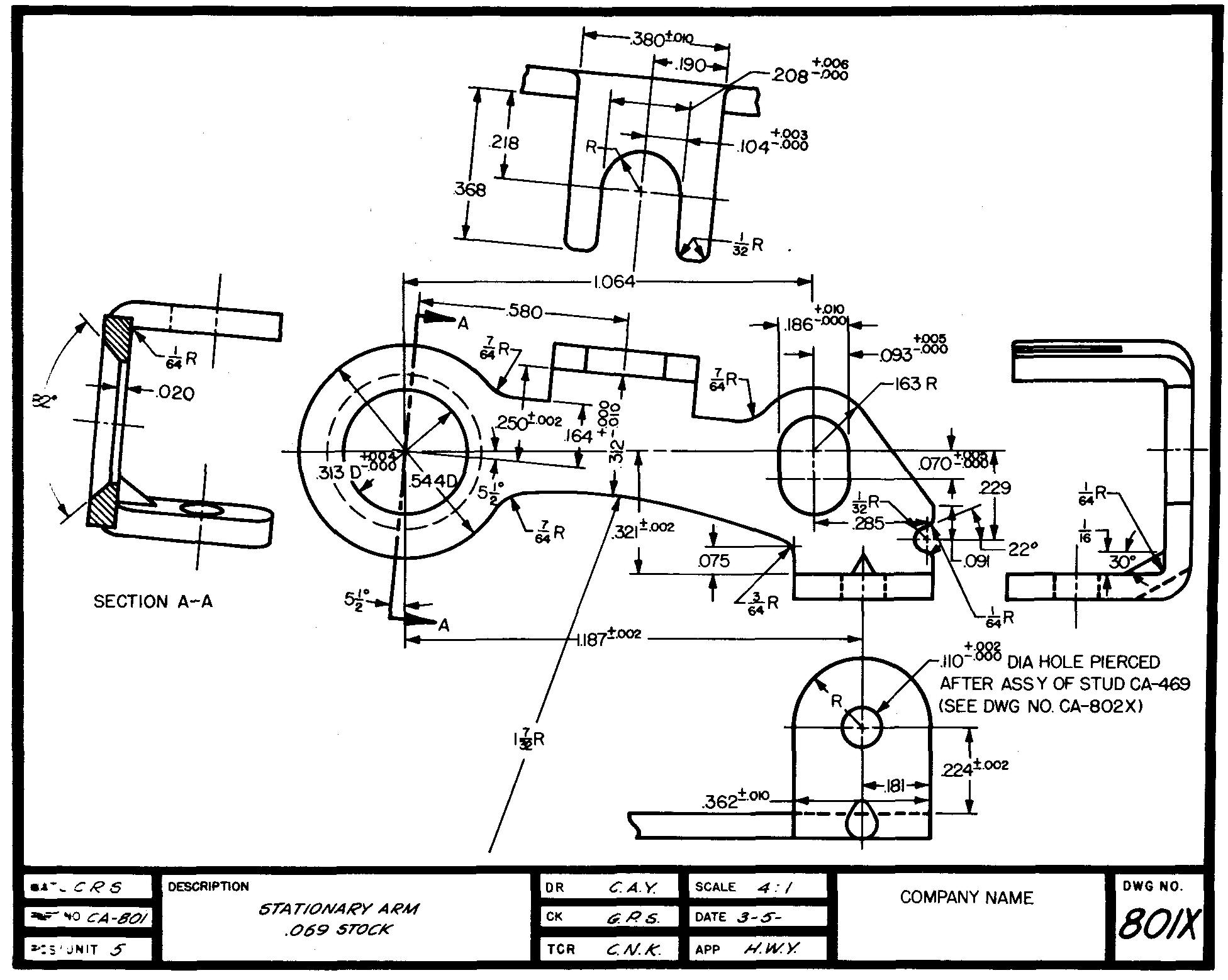
Figure 10-1 is a detail drawing of a complicated machine part.
Fig. 10-1. A complicated machine part
Almost every dimension shown on the drawing was obtained by using basic arithmetic processes.
The draftsman began by selecting a suitable drawing scale (in this case four times size). To check the suitability of the scale, he used arithmetic which involved dividing, multiplying, adding, and subtracting numbers. He then knew the views would fit neatly on the sheet.
Before he could draw the views of this part, the draftsman had to work out the distances and sizes for each of the elements of the part. After the views were drawn, the draftsman used these calculations to apply the dimensions to the drawings.
The draftsman must remember to give all the dimensions necessary to make the part. The shopman should be able to make the part from the drawing without having to work out any of the dimensions for himself.
In preparing the drawing in Fig. 10-1, the draftsman also worked out the location of the holes and of the other elements of the part. They were carefully checked to prevent the possibility of one element interfering with another. The draftsman also needed to use arithmetic to obtain the information for the drilling, reaming, and threading notes.
As you can see, the knowledge of basic mathematics is so important to the machine draftsman that he could not do his job without it.
This section will illustrate some of the more common mathematical terms, formulas, and processes which are used by machine draftsmen in their work. Practical examples are given in each case, relating the mathematics to specific drawing situations.
Problem solving
It is important for the machine draftsman to develop an orderly procedure in working out problems. Most successful draftsmen begin the solution of a problem by preparing a freehand sketch, as shown in Fig. 10-2.
Fig. 10-2. A problem sketch
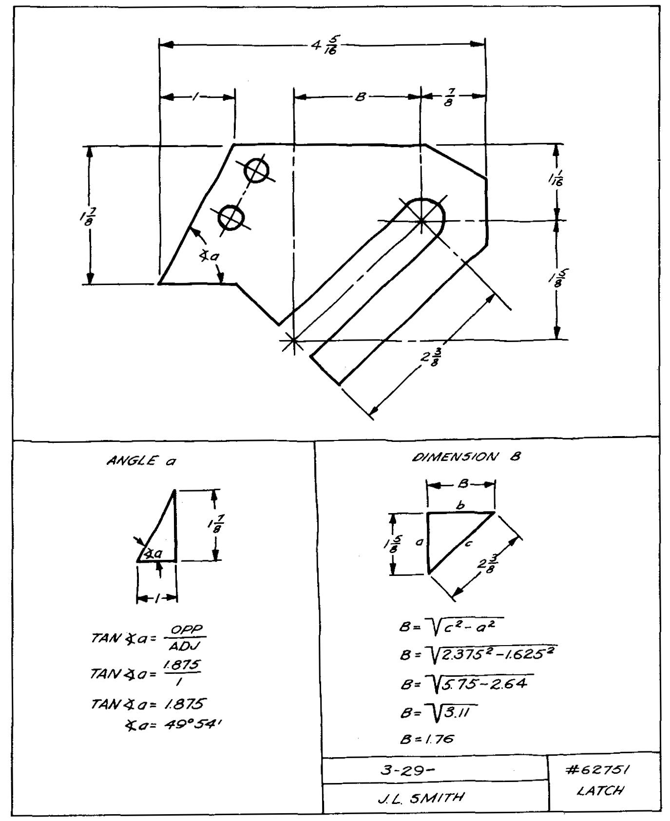
On this sketch the draftsman can show all the known information. He can relate this information to the factors which are unknown at the start of his work (angle a and dimension B in Fig. 10-2).
Such an approach is called setting up the problem. In some cases it may be helpful to use various colors of pencil lead to represent required information on the sketch.
On the sheet with the sketch, the draftsman lists all the necessary formulas he expects to use. To simplify the work, the draftsman lists each step of his process from the start to the final answer. This list aids the draftsman in checking back if such a check becomes necessary some time later.
A title should be added to the sketch, giving the part name and number, the draftsman's name, and the date on which the problem was solved.
Any other appropriate
information should also be listed.
Most companies provide draftsmen with pads
of 8-1/2-inch by 11-inch paper for working out problems. The paper may be plain,
regularly ruled, or ruled for graphs.
After all of the drawings of a machine or structure are complete, they are carefully inspected by an experienced draftsman or engineer, called a checker. Each line, note, and dimension is thus double checked for accuracy and correctness.
It is wise for the draftsman to retain his figures and sketches until after the final drawings have been checked and released to the shop. Saving the figures makes it possible to refer to them should the checker discover an error or should he have any questions regarding them.
Checkers frequently desire proof of drafting calculations. The advantages obtained by saving calculations cannot be overemphasized.
Changing fractions to decimals
In working out problems involving fractional numbers such as 1/2, 29/32, and 3-5/16, it is often more convenient to change the fractions to their decimal equivalents.
This may be quickly done by using the table shown in Fig. 10-3. Numbers from 1/64 through 1 are given on this table together with their decimal equivalents.
Fig. 10-3. A decimal conversion chart
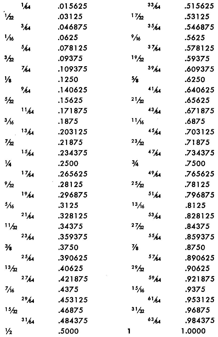
A common fraction can be changed to its equivalent decimal by dividing the numerator of the fraction by the denominator. For example, to find the decimal equivalent of 5/8, divide 5 by 8.
The answer is 0.625.
Example
Find the decimal equivalent for each of the following:
a. 1/2 inch. b. 2-3/4 inch,
c. 7/8 inch. d. 11-3/16 inch,
e. 19/32 inch. f. 6-15/64 inch.
Solution
For a, find the fraction 1/2 in the first column of Fig. 10-3. Read across to the right for the decimal equivalent.
a. 1/2 in. = 0.5000 in.
For b, find the fraction 3/4 in Fig. 10-3 and read across for the decimal equivalent. Since 2-3/4 inches includes the whole number 2, the 2 must be included with the decimal equivalent.
The decimal equivalents of the fractions given in the example are:
b. 2-3/4 in. = 2.7500 in.
c. 7/8 in. = 0.8750 in.
d. 11-3/16 in. = 11.1875 in.
e. 19/32 in. = 0.59375 in.
f. 6-15/64 in. = 6.234375 in.
Working with constants
Certain known unchanging values, called constants, simplify the arithmetic of many formulas. Constants are used only for regular or proportional geometric figures such as triangles, squares, rectangles, and circles.
For example, in the equilateral triangle shown in Fig. 10-4, note that the altitude is given as equal to 0.866s.
Fig. 10-4. An equilateral triangle
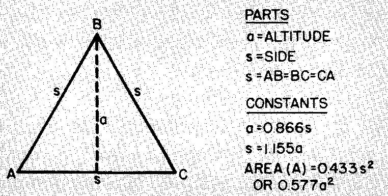
This means that every equilateral triangle, regardless of its size, has an altitude which is equal to 0.866 times or 86.6 percent of the measurement of a side of that triangle.
Most of the examples to follow use constants as shortcuts in solving for unknown parts of various regular figures.
Equilateral triangles
The equilateral triangle, a regular figure with three equal sides and three equal angles of 60°, is shown in Fig. 10-4.
Figure 10-4 also gives some formulas for the equilateral triangle. Note the use of constants in these formulas.
Example thread dimensions
What is the depth of thread for the 1/4-20 NC thread shown in Fig. 10-5?
fig. 10-5.
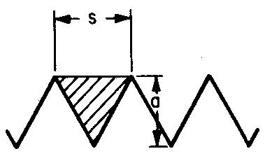
Solution
a = depth of thread, s = pitch of thread. For 20 threads per inch, the pitch (s) equals 1/20 of an inch, or 0.05 inch.
As shown in Fig. 10-4, a = 0.866.S.
Substituting 0.05 for s:
a = (0.866) (0.05), or 0.866 times 0.05.
a = 0.0433 in.
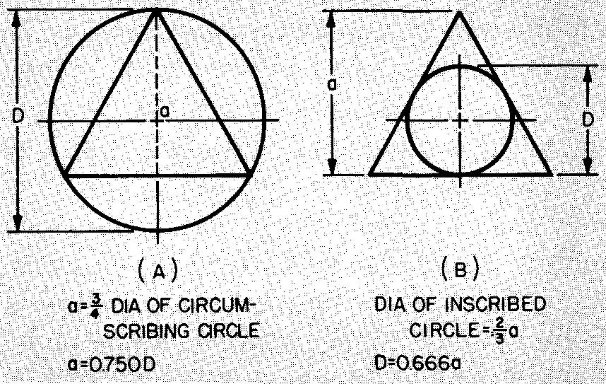
Equilateral-triangle and circle relationships
The relationships between equilateral triangles and certain circles are shown in Fig. 10-6.
Fig. 10-6. Equilateral-triangle and circle relationships
Example 1 dimensioning for bolt holes
Calculate dimensions a, b, and c in Fig. 10-7 A.
Fig. 10-7.
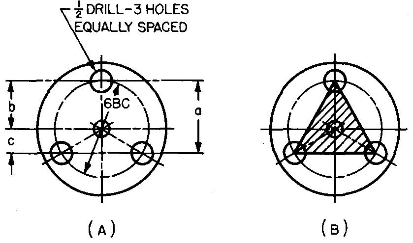
Solution
Lines drawn connecting the centers of the three holes spaced equally on a bolt circle form an equilateral triangle, as shown in Fig. 10-7B.
STEP 1: As shown in Fig. 10-6, a = 0.75D.
Substituting 6 for D (given in Fig. 10-7A): a =(0.75) (6). a = 4.5 in.
STEP 2: As shown in Fig. 10-7, b = 6/2. b = 3 in. STEP 3: As shown in Fig. 10-7, c — a — b.
Substituting 4.5 for a (STEP 1) and 3 for b (STEP 2): c = 4.5 - 3. c = 1.5 in.
Example 2 dimensioning a drawing
Calculate dimension x in Fig. 10-8.
Fig. 10-8.
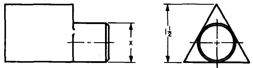
Solution
As shown in Figs. 10-6 and 10-8, D = 0.666a and D = x.
Substituting x for D: x = 0.666a.
As shown in Fig. 10-8, a = 1.5 in.
Substituting 1.5 for a: x= (0.666) (1.5). x = 0.999 in.
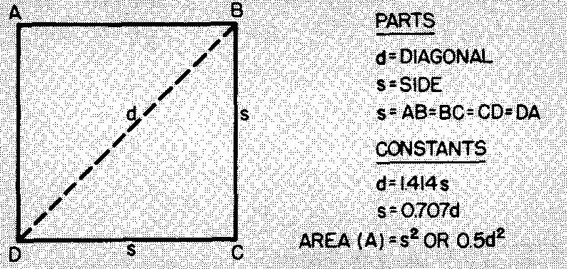
Squares
A square is a rectangle with four equal sides. (A rectangle is a four-sided figure with angles of 90°.)
Figure 10-9 gives some formulas for squares.
Fig. 10-9. A square
example 1 calculating corner clearance for a square nut
What is the distance across the corners of the square nut shown in Fig. 10-10?
Fig. 10-10.
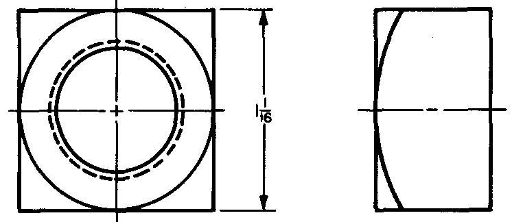
Solution
As shown in Fig. 10-9, d = 1.4145.
Substituting 1.0625 for s (given in Fig. 10-10): d = (1.414)(1.0625). d = 1.502 in.
Example 2 dimensioning a drawing
Calculate dimension x in Fig. 10-11.
Fig. 10-11.
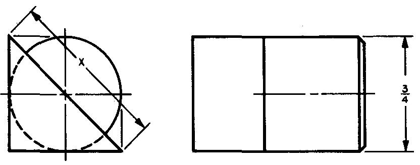
Solution
As shown in Fig. 10-9, d = 1.414s.
Substituting 0.75 for s (given in Fig. 10-11):
d= (1.414) (0.75). d = 1.061 in.
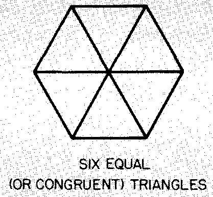
Hexagons
Figures with six equal sides and six equal angles of 120° are called regular hexagons. Figure 10-12 gives some formulas for hexagons. A regular hexagon may be divided into six equal (or congruent) equilateral triangles as shown in Fig. 10-13.
Fig. 10-12. A hexagon
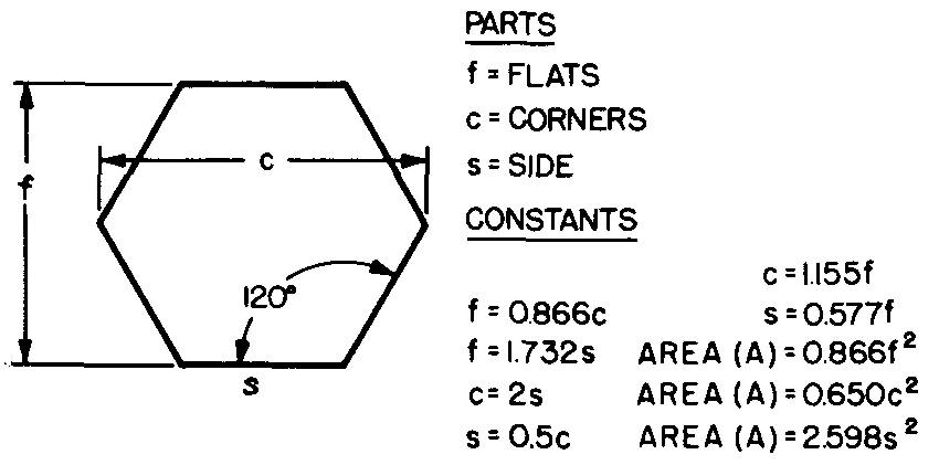
Fig. 10-13
Example 1 dimensioning for bolt holes
In Fig. 10-14A, six bolt holes are equally spaced on a 6-inch diameter bolt circle. Calculate dimensions s and x.
Fig. 10-14.
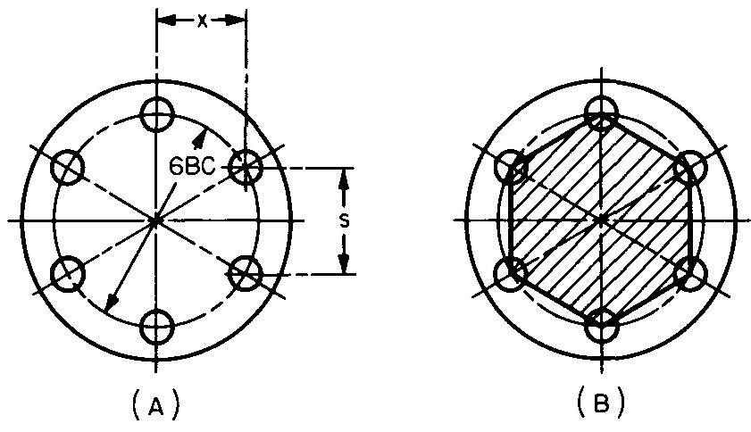
Solution
Lines connecting the centers of the six adjacent holes spaced equally on a bolt circle form the shaded hexagon shown in Fig. 10-14B.
STEP 1: As shown in Fig. 10-12: 5 = 0.5c.
Substituting 6 for c (given in Fig. 10-14): s=(0.5)(6). s = 3 in.
STEP 2: Dimension x corresponds to the altitude of an equilateral triangle.
As shown in Fig. 10-4, a = 0.866s.
Figure 10-14 gives x = a.
Substituting 0.866s for a: x = 0.866s.
Substituting 3 for s (from STEP 1): x = (0.866) (3). x = 2.598 in.
Example 2 calculating corner clearance for a hexagonal nut
What is the distance across the corners of the hexagonal nut shown in Fig. 10-15?
Fig. 10-15
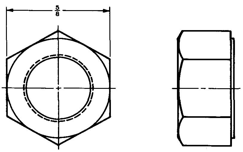
Solution
As shown in Fig. 10-12, c = 1.155f.
Substituting 0.625 for / (given in Fig. 10-15): c= (1.155)(0.625). c = 0.722 in.
Octagons
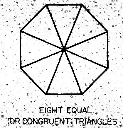
A figure with eight equal sides and eight equal angles of 135° is called a regular octagon. Figure 10-16 gives formulas for the octagon. A regular octagon may be divided into eight equal (or congruent) triangles as shown a Fig. 10-17.
Fig. 10-16. An octagon
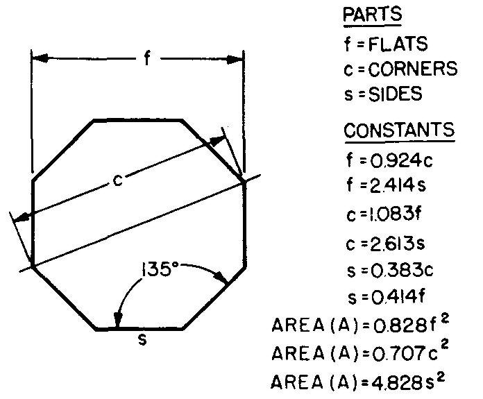
Fig. 10-17
Example 1 dimensioning a drawing
An octagon is to be cut from a piece of 3-3/4-inch square stock as shown in Fig. 10-18. Solve for dimension x.
Fig. 10-18
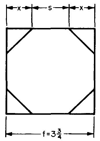
Solution
STEP 1: As shown in Fig. 10-16, s = 0.414f. Substituting 3.75 for f (given in Fig. 10-18):
s= (0.414) (3.75).
s= 1.553 in.
STEP 2: As shown in Fig. 10-18, f — s = 2x.
Substituting 3.75 for / (given
in Fig. 10-18) and 1.553 for s (from STEP 1): X = 3.75 - 1.553 / 2
x=
1.099 in.
Example 2 dimensioning for bolt holes
Calculate dimensions f, a, and s and angle b in Fig. 10-19.
Fig. 10-19.
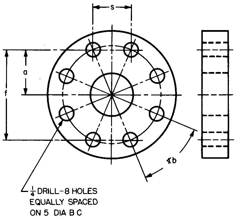
Solution
The note drawn to the holes in Fig. 10-19 states that there are eight holes equally spaced. Lines drawn connecting the centers of the eight holes form an octagon.
The opposite holes are spaced 5 inches apart. (The bolt circle has a diameter of 5 inches.)
This represents c in Fig. 10-16. STEP 1: As shown in Fig. 10-16, / = 0.924c.
Substituting 5 for c (given in Fig. 10-19): f= (0.924) (5).
f = 4.62 in.
STEP 2: As given in Fig. 10-19, a = f/2
Substituting 4.62 for f (from STEP 1):
a = 4.62 / 2
f = 2.31 in.
STEP 3: As shown in Fig. 10-16, s = 0.383c. Substituting 5 for c (given in Fig. 10-19): 5= (0.383)(5). s = 1.915 in.
STEP 4: Angle b measures the angular spacing between adjacent holes.
There are eight holes spaced equally on a circle. A circle contains 360°.
Therefore
<b = 360° / 8 = 45°.
Trigonometry
The techniques of trigonometry may be used to find the measurement of the sides and angles of triangles. Trigonometry is an extremely valuable tool to the machine draftsman, since a great many drawing and shop problems may be solved by applying trigonometric relations.
Notice how we continue to use basic arithmetic in solving the trigonometric problems in the following examples of drafting problems.
We shall discuss problems which involve only the right triangle. A right triangle always has one angle of 90°. Notice the terms which describe each side of the triangle in Fig. 10-20A.
Fig. 10-20. A right triangle
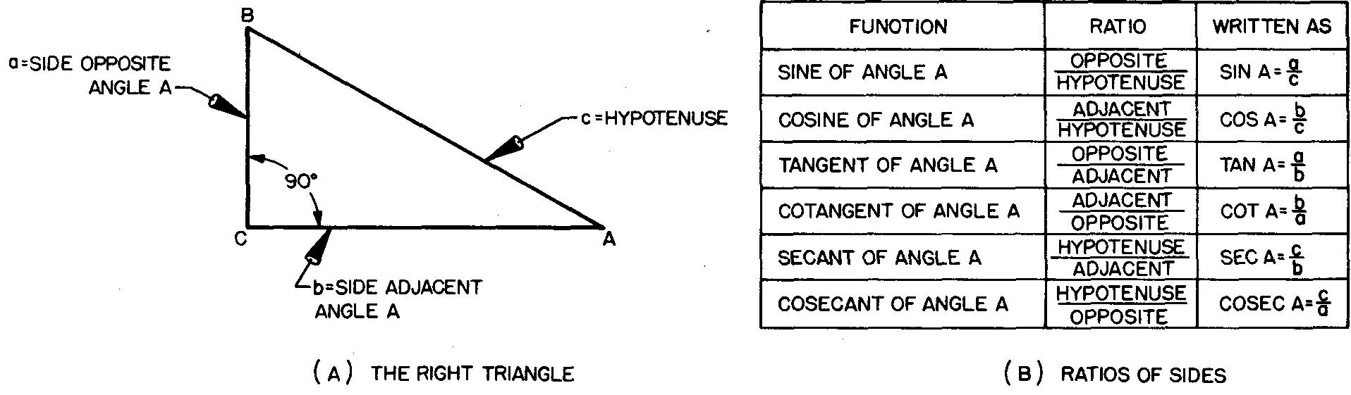
Side a is opposite angle A and side b is adjacent to (along side of) angle A. Side c is called the hypotenuse. The hypotenuse is always the longest side of a right triangle. The sides forming the right angle are called legs.
Since the sum of the measurements of the three angles in any triangle is always 180°. it is possible to find the measurement of either acute angle (angle A or angle B) if the measurement of the other angle is known. In a right triangle, angle C measures 90°.
Therefore the sum of angles A and B always totals 90°. Thus if angle B is known to be 60°. angle A is 30°.
Each of the three sides of a triangle may be related to each of the other sides as a ratio. A ratio is a comparison of two numbers. In ratios of measures, the numbers compared must measure like items such as speed, time, or sides of a triangle.
For any triangle, there are six possible ratios. For right triangles the six ratios are determined from the size of angle A. These ratios are listed in Fig. 10-20B.
Each ratio is called a trigonometric function of angle A. As the measurement of angle A changes, the value of each trigonometric function also changes.
In a right triangle, the measurement of angle A must be greater than 0° and less than 90°. Angle A may be any measurement between these. Mathematicians have accurately worked out a table of constants for the ratios of the sides of right triangles for each of these angles.
They have calculated the values of the ratios for all angles from 0° to 90°. These values are called natural trigonometric functions. They are found in Table 2.
As you examine Table 2, you will see that each section of the table gives the values for a set of complementary angles.
That is, the angle named at the top of that section of the table plus the angle named at the bottom of that section plus the 60 minutes listed at the edges of that section of the table equal 90°.
You will also notice that the names of the functions occupy different positions at the top and the bottom of each column.
Similarly, the minutes are in reverse order from top to bottom at the right and left sides of each section of the table.
The information given by this table differs according to whether you read down the columns or up the columns.
It is important to know in which direction to read. It is also important to be sure that the table headings used give the information for the direction in which the table was read.
The following examples will clarify the use and reading of Table 2.
The relationships between the parts of a right triangle can be used to find the measurements for all parts of a given right triangle as long as a minimum number of facts are known.
As we have seen, we can find the measurement of one acute angle if the measurement of the other angle is known. If we know the measurement of one side and one acute angle, we can solve for the measurements of the other sides.
And if we know the measurements for two legs, we can find the third side and both acute angles.
We have learned that dimensions on detail drawings must be accurately worked out by the machine draftsman. The following examples illustrate typical practical uses for trigonometry in working out such dimensions.
As you examine the examples, try to see how the application of a right triangle simplifies the problem.
The draftsman's skill in applying trigonometry to machine drawings depends upon his ability to break up problems into right triangles, so that the various parts of each area may be more readily observed and solved.
Example 1 calculating angles
Calculate angle A in Fig. 10-21.
Fig. 10-21.
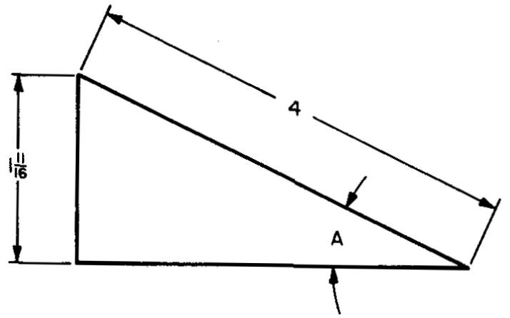
Solution
Figure 10-21 gives the measurements for two sides of the triangle.
We know the opposite side (1.6875 in.) and the hypotenuse (4 in.) and we wish to find angle A.
From Fig. 10-20 we select a ratio involving sides a and c.
We could use either the sine or the cosecant.
For this example we will select the sine ratio.
STEP 1:
As shown in Fig. 10-20, sin A = a/c.
Substituting 1.6875 for a and 4 for c (given inFig. 10-21): sin A = 1.6875/4. sin .4 = 0.42188.
STEP 2:
To find angle A, we must find the computed ratio (or the number closest to it in value) in Table 2, Natural Trigonometric Functions.
Looking under the columns labeled sin and cos, we find 0.42183 and 0.42209.
Since our computed ratio, 0.42188, is closer in value to 0.42183, we will use this value as our sine ratio.
This value was labeled sin at the top left-hand side of this section of the table.
There fore we will take as our measurement in degrees the top left-hand label, 24°, and we will read down the left-hand side to find the minutes.
Our selected sine ratio, 0.42183, is opposite to 57'.
SUMMARY:
We computed sin A = 0.42188, which is approximately 0.42183. sin 24°57' = 0.42183.
Therefore A = 24° 5 7', to the nearest whole minute.
Example 2 finding a leg of a right triangle
Calculate side a in Fig. 10-22.
Fig. 10-22
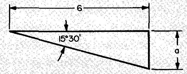
Solution
Figure 10-22 gives the measurement for angle A and for side b.
From Fig. 10-20 we select the tangent ratio. We will solve for side a.
STEP 1:
As shown in Fig. 10-20, tan A = a/b.
Substituting 15° 30' for < A and 6 for b (given in Fig. 10-22): tan 15°3O' = a/6. a= (tanl5°30')(6).
STEP 2:
Find tan 15°30' in Table 2.
Read down the column to find 30' on the left edge of the table, then across to read the value for 30' under the top right-hand, heading tan. tan 15°30' = 0.27732.
Substituting 0.27732 for tan 15°3O' in the equation from STEP 1: a = (0.27732) (6). a = 1.664 in.
Example 3 applying a right triangle
Calculate dimension x in Fig. 10-23.
Fig. 10-23
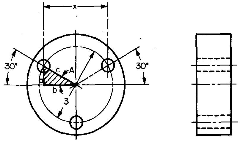
Solution
STEP 1: Figure 10-23 gives c equal to the radius of the bolt circle, or c = 3/2.
c= 1.5 in.
STEP 2: Figure 10-23 shows that x = 2b.
To find b, use the cosine ratio from Fig. 10-20:
cos A = b/c, or b = (cos A) (c).
Substituting 30° for < A (given in Fig. 10-23) and 1.5 for c (from STEP 1): b= (cos30°)(1.5).
From Table 2, under the top left heading, cos, even with the left-hand heading of 0', reading down, we find cos 30° = 0.86603, which is substituted for cos 30°:
b= (0.86603) (1.5). b = 1.299 in.
STEP 3:
Figure 10-23 gives x = 2b.
Substituting 1.299 for b (from STEP 2): x= (2) (1.299). x = 2.598 in.
Example 4 applying a right triangle
Calculate dimension x in Fig. 10-24.
Fig. 10-24.
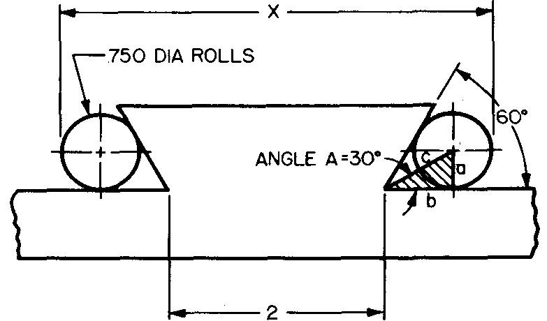
Solution
Dimension x equals 2 inches plus 2 times the side b of the shaded triangle shown in Fig. 10-24 plus 2 times the radius of the roll.
STEP 1:
From Fig. 10-24, we have a = the radius of the roll, or 0.750 / 2, or 0.375 inches and A = half of the 60° angle, or 30°.
The 60° angle is bisected, or divided in half, by c.
From Fig. 10-20, we select the cotangent ratio: cot A =b/a.
Substituting 30° for A and 0.375 for a:
cot 30° = b / 0.375
b = (cot 30°) (0.375).
From Table 2, reading down, we find cot 30° = 1.7320.
Substituting 1.7320 for cot 30°: b= (1.7320)(0.375). b = 0.650 in.
STEP 2: x = 2 + 2b + 2r.
Substituting 0.650 for b and 0.375 for r. x = 2 + (2) (0.650) + (2) (0.375). x = 4.050 in.
Example 5 applying a right triangle
Calculate the taper angle in Fig. 10-25.
Fig. 10-25
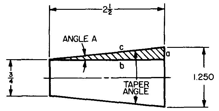
Solution
The taper angle is equal to 2 times angle A of the shaded triangle.
From Fig. 10-20, we select the tangent ratio: tan A = a/b
STEP 1:
From Fig. 10-25, we see that a is equal to half the difference between 1.25 and 0.75.
a = (1.25 - 0.75) / 2 = 0.5 ' / 2 or 0.25 in.
b = 2.5 (given in Fig. 10-25).
Substituting: tan A = 0.25 / 2.5
tan A = 0.10000.
Looking in Table 2 for the tangent value closest to 0.10000, we find 0.09981 and 0.10011.
Our computed value, 0.10000, is closer to 0.10011.
We select the values for the angle from the top and left side of the table.
A =5°43'.
STEP 2: T = 2(A).
Substituting 5 °43' for A:
T= (2)(5°43') or 11°26'.
Example 6 right triangle
Calculate the pitch cone angle of the gear shown in Fig. 10-26.
Fig. 10-26.
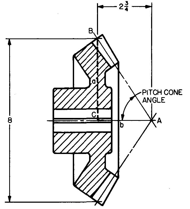
Solution
The pitch cone angle is equal to angle A of triangle ACB.
From Fig. 10-26, we see that side a = 8/2, or 4, and b = 2.75.
From Fig. 10-20, we select the tangent ratio: tan A = a/b.
Substituting: tan A = 4 / 2.75
tan A = 1.4545.
Looking in Table 2 under the columns labeled tan, we find 1.4541 and 1.4550. Our computed ratio is closer to 1.4541.
We select the values for the angle from the bottom and right sides of the table, opposite 1.4541, reading the minutes up from the bottom.
A = 55°29'.
Solving for the sides of right triangles
In some problems involving right triangles, neither angle A nor angle B is known. It is possible to solve these triangles by using trigonometric relationships as shown in Sec. above.
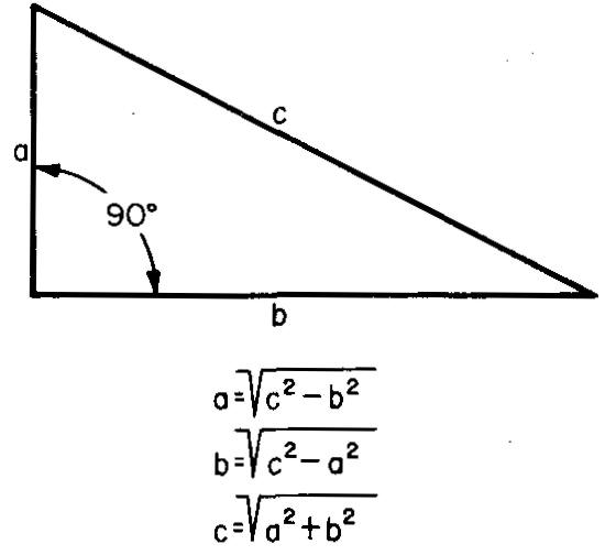
However, it is often simpler to use arithmetic to find one side of a triangle when the other two sides are known. This shorter way uses the formulas in Fig. 10-27.
Fig. 10-27
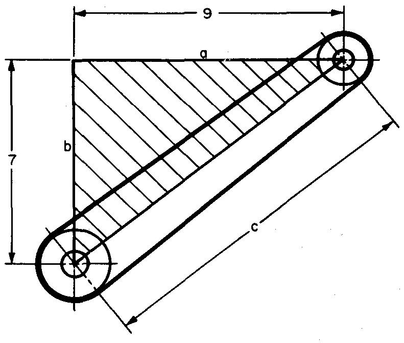
Example finding dimensions for pulley centers
Calculate dimension c in Fig. 10-28.
Fig. 10-28.
Solution
From Fig. 10-27, c = √(a2 + b2)
Substituting 9 for a and 7 for b (given in Fig. 10-28):
c = √(92 + 72)
From Table 3, Functions of Numbers, find the square root of 130. c= 11.4018 in.
Solving for the area of right triangles
Area is the measurement of the surface bounded by any closed figure.
Standard area measurements include square inches and square feet. Figure 10-29 gives the formula for finding the area of right triangles when the measurements of two sides are known.
Fig. 10-29.
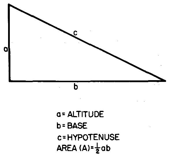
Example finding the area of right triangles
Calculate the area of a right triangle in which the altitude = 1-1/4 inches and the base = 2-1/2 inches.
Solution
As shown in Fig. 10-29, A = 1/2 ab.
Substituting 1.25 for a and 2.5 for b:
A = (1.25)(2.5) / 2 = 1.5625 sq. in.
Isosceles triangles
A triangle with two equal sides and two equal angles is called an isosceles triangle.
Figure 10-30 shows that the altitude bisects the isosceles triangle into two equal right triangles.
Fig. 10-30. An isosceles triangle
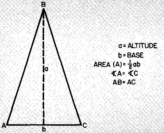
Example finding the area of isosceles triangles
Calculate the area of an isosceles triangle in which the base = 8 inches and the altitude = 10 inches.
Solution
As shown in Fig. 10-30, A = 1/2 ab.
Substituting 10 for a and 8 for b:
A = (10)(8) / 2 = 40 sq. in.
Scalene, or oblique, triangles
Any triangle with three unequal sides is a scalene triangle. Scalene right triangles may be solved as discussed.
The formulas for other scalene triangles are given in Fig. 10-31.
Fig. 10-31. a scalene, or oblique, triangle
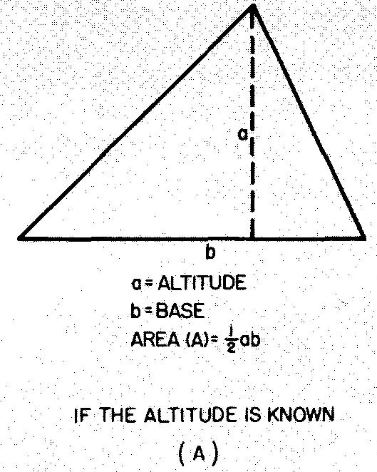
Example 1 finding the area of scalene triangles
Calculate the area of the triangle in Fig. 10-32.
Fig. 10-32
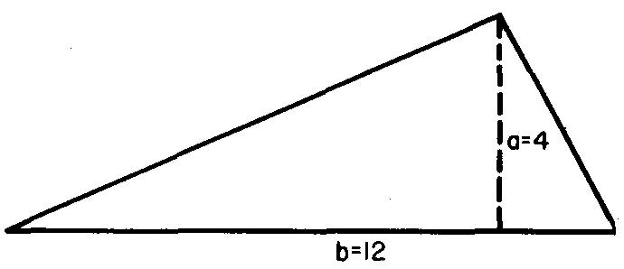
Solution
Since the altitude is known, use the formula in Fig. 10-31 A: A = 1/2 ab.
Substituting 4 for a and 12 for b (given in Fig. 10-32):
A = (4)(12) / 2 =24 sq. in.
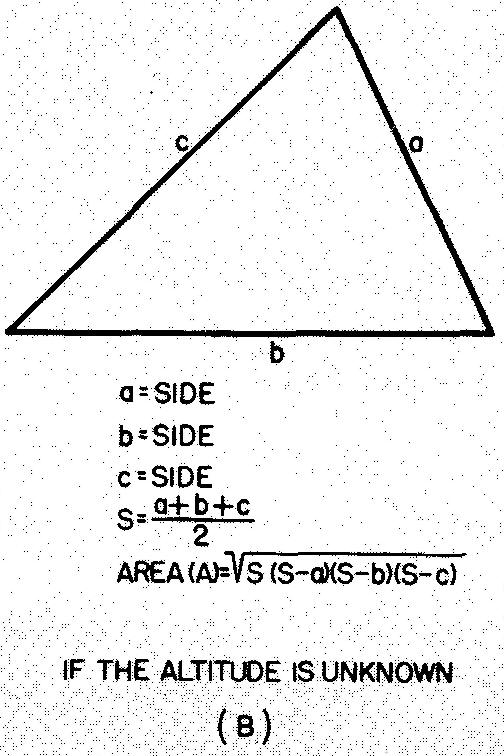
Example 2 finding the area of scalene triangles
Calculate the area of the triangle in Fig. 10-33.
Fig. 10-33
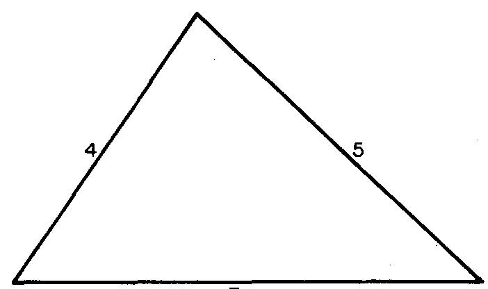
Solution
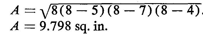
Since the altitude is unknown, use the formula in Fig. 10-31B:
![]()
Substituting 5 for a, 7 for b, 4 for c, and 8 for 5 (given in Fig. 10-32. 5 is computed from:
S = (a + b + c) / 2
Trapezoids
Four-sided figures with two and only two sides parallel are called trapezoids. Figure 10-34 gives the formula for the area of trapezoids.
Fig. 10-34. U trapezoid
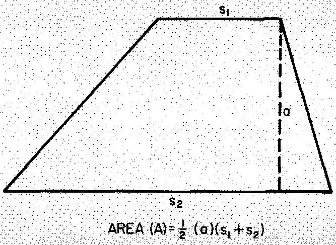
Example finding the area of trapezoids
Solution
As shown in Fig. 10-34
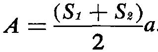
Substituting 8 for S1, 12 for S2, and 6
for a (given in Fig. 10-35):
Fig. 10-35
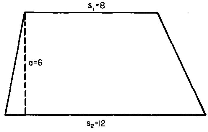
A = ((8 + 12)/2) x 6
A = 60 sq. in.

![]()