Forming parts by pressure
Introduction
We have studied forming parts by machining and by casting. Parts may also be formed to the desired shape by forging, by the process of powder metallurgy, and by the process of pressing from metal sheets.
While each of these processes differs in the method of manufacture, there is a definite similarity. In each case, pressure must be applied to a form of metal, thus forcing or squeezing the metal into cavities which form the shape of the metal parts. The metal may be hot or cold or even powdered at the time the pressure is applied.
Forged parts
Parts produced by pressing or hammering to the desired shape are called forgings. Blacksmiths have used the basic techniques of forging metals for many centuries.
Originally suits of armor, weapons, tools, horseshoes, and so on were hand forged. The essential difference between the work of the village smithy and modern industrial forging methods is in the mechanization and refinements of the process. Practically all industrial metals and alloys can be forged. These include aluminum, brass, bronze, copper, magnesium, steel, and titanium.
The forging process squeezes the metal into shape. Forged parts are found to be less porous than castings, and they are extremely strong. The greater strength is due to the fiber structure which is produced in forgings.
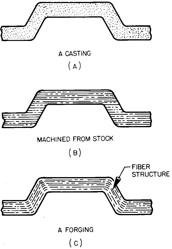
The structure can be compared to the grain in wood which is often called the figure. In metals, the fiber structure can be made visible to the eye by polishing a flat area and then chemically etching the polished surface. The structure of some metal parts may be observed without prior polishing and etching if the surface is already smooth.
Figure 15-1 contrasts the structure of metal samples which were produced by casting, by machining from solid stock, and by forging. Forged parts have an unbroken fiber flow which generally follows the contour, or shape, of the part.
Fig. 15-1. Grain structure
For this reason parts requiring resistance to sudden shock and stress are usually forged. Parts commonly made by forging include aircraft and automobile engine and frame parts and wrenches, bolts, and rivets.
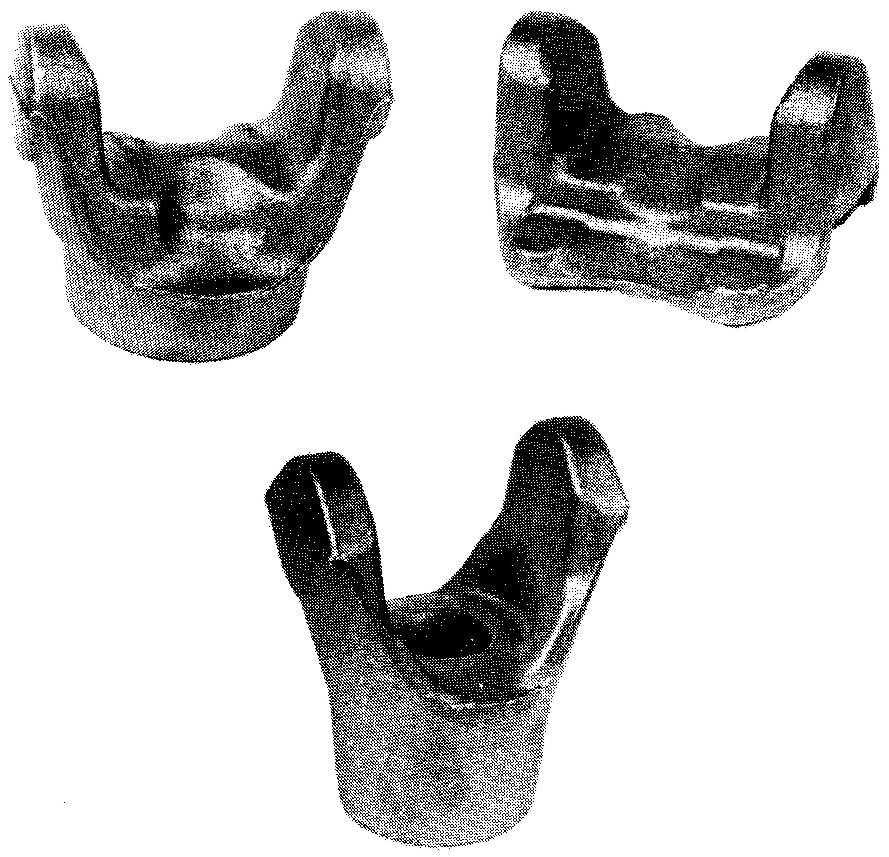
Figure 15-2 shows examples of parts produced by this process.
Fig. 15-2. Parts produced by forging
Metals may be forged while either hot or cold. Generally, the harder metals must be hot forged. Some of the softer metals may be cold forged without previous heating. Both hot and cold forgings are made on the same kinds of presses.
Three general methods of producing forgings are commonly used: smith forging, drop forging, and press forging.
Smith forging
The steam hammer or hydraulically operated hammer, shown in Fig. 15-3, is the principal type of machine used in smith forging. The process is known as open die forging.
Fig. 15-3. Open die forging
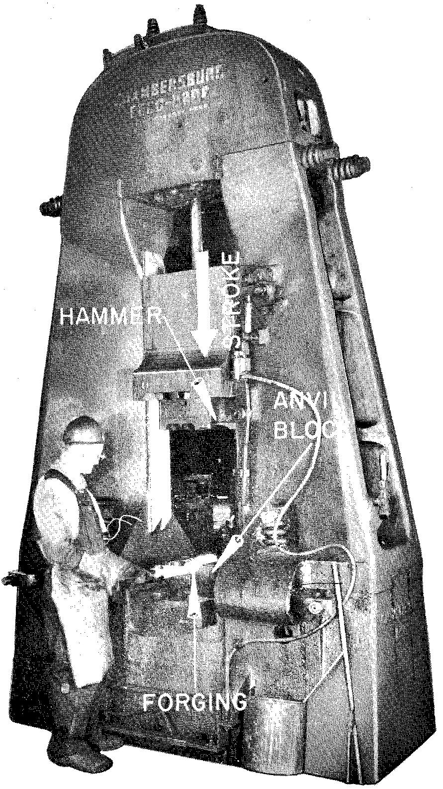
The hammer is fastened to the end of a piston rod and travels between guides. The hammer may weigh from one-half ton to thirty tons. The workpiece is first heated and is then manually moved about during forging on a flat anvil block. The piece is thus hammered into the required shape.
Drop forging
Drop forgings are made by repeated blows of a drop hammer, shown in Fig. 15-4.
Fig. 15-4. The drop hammer
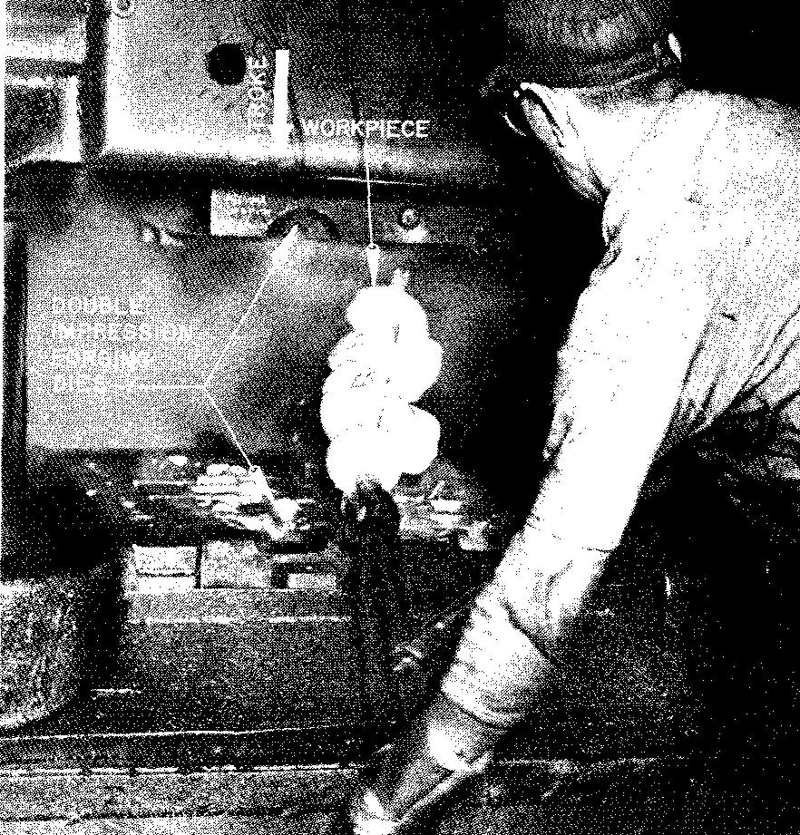
The process is known as closed die forging. Two dies are used. Each die has an impression cut into it corresponding to the outline shape of the required part.
The upper die is fastened to the ram (striking weight), and the lower die is fastened to the anvil block. The heated metal piece is inserted between the dies, and as the ram is dropped, the metal is caused to flow into the impression of the dies. The dies may contain a single impression or two or three impressions.
For example, for a die having three impressions, the part may be hammered in the first impression to its general size and shape. The second impression forms the part closer to the desired shape and size, and the final impression forms the finished forging.
Press forging
The press forging method, shown in Fig. 15-5, produces forgings by inserting metal between the dies, similarly to the drop forging process.
fig. 15-5. The press forging method
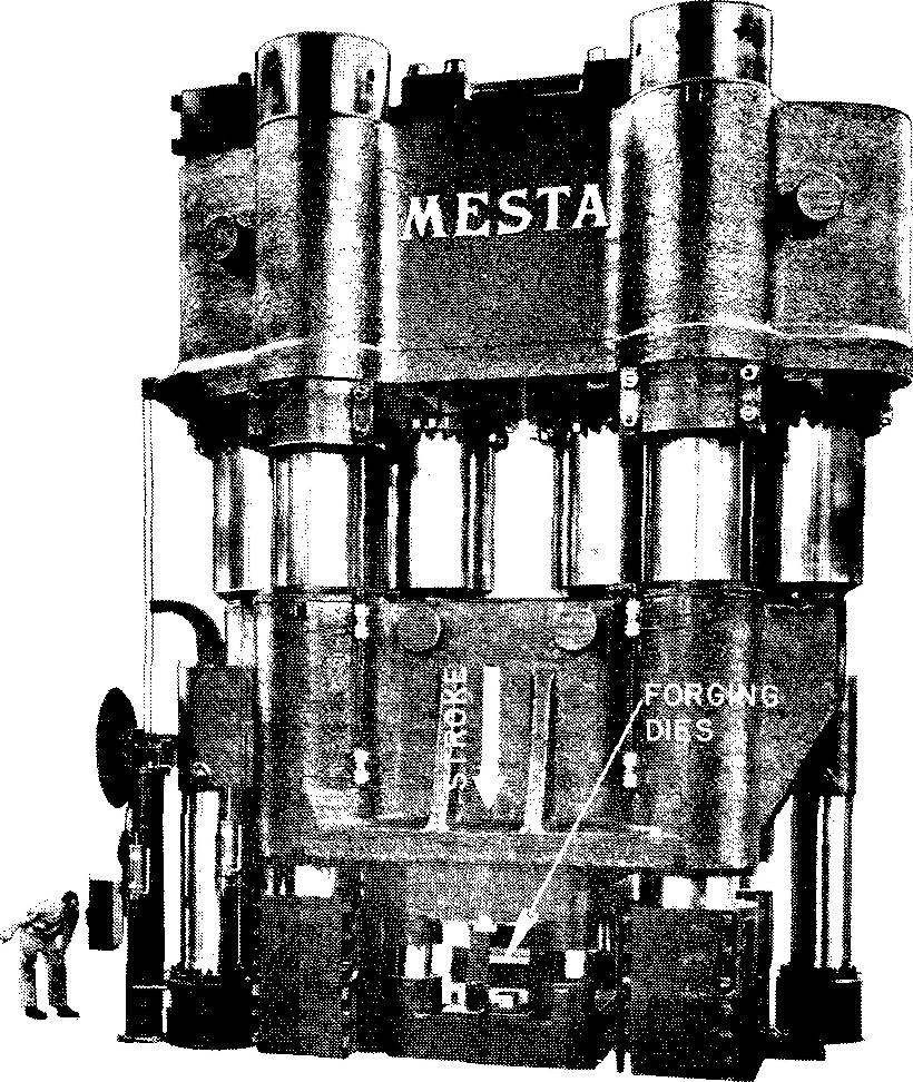
Pressure is first applied by a striking blow from the hammer on the metal. At the end of the blow, additional pressure is steadily applied, which pushes and squeezes the metal into the impression of the dies. On some of the larger presses, the metal is formed by an even pressure throughout, with no striking force.
Forging dies
It is important to understand that the shape of the final forging is always determined by the impression which has been previously machined into the dies. Diemaking is a time-consuming process which requires great skill; therefore the making of dies is expensive. Dies must be accurately made.
An undiscovered error may ruin as many as several thousand forgings, which is the usual quantity to be made on a production basis.
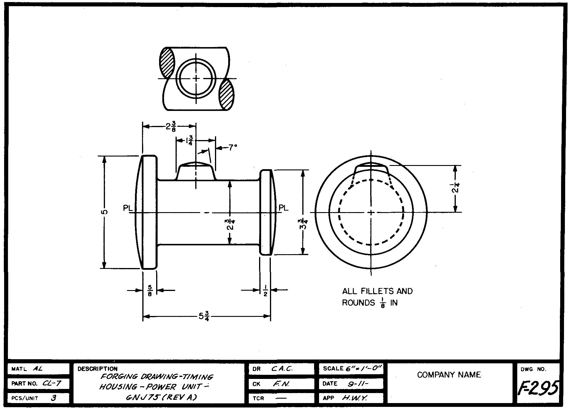
Forging drawing practices
Many industries prefer to have two separate drawings made of a forged part. One drawing, the forging drawing, is prepared solely for the diemaker. Only those dimensions of the part which are necessary to make the die are given, as shown in Fig. 15-6. The drawing shows the part after forging but before machining.
fig. 15-6. a Forging drawing
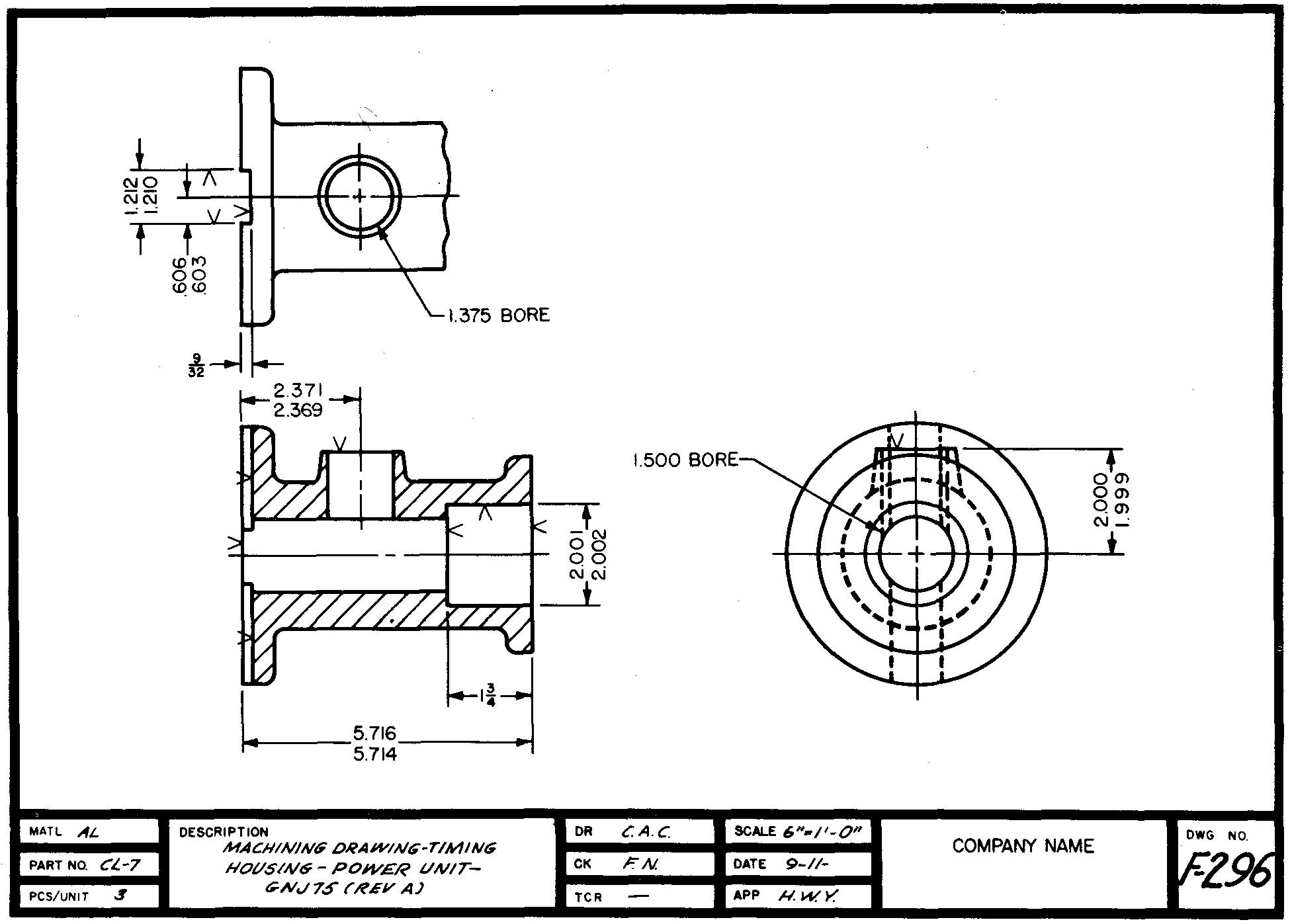
A second drawing, the machining drawing, is prepared for the machinist. Only those dimensions which apply to the required machining operations following the forging operations are given, as shown in Fig. 15-7.
fig. 15-7. a Machining drawing
Industrial practices vary slightly in the way in which the drawings should be prepared. While some companies prefer separate drawings for forging and machining, other companies prepare only one drawing, Fig. 15-8.
fig. 15-8. a Forging and machining drawing
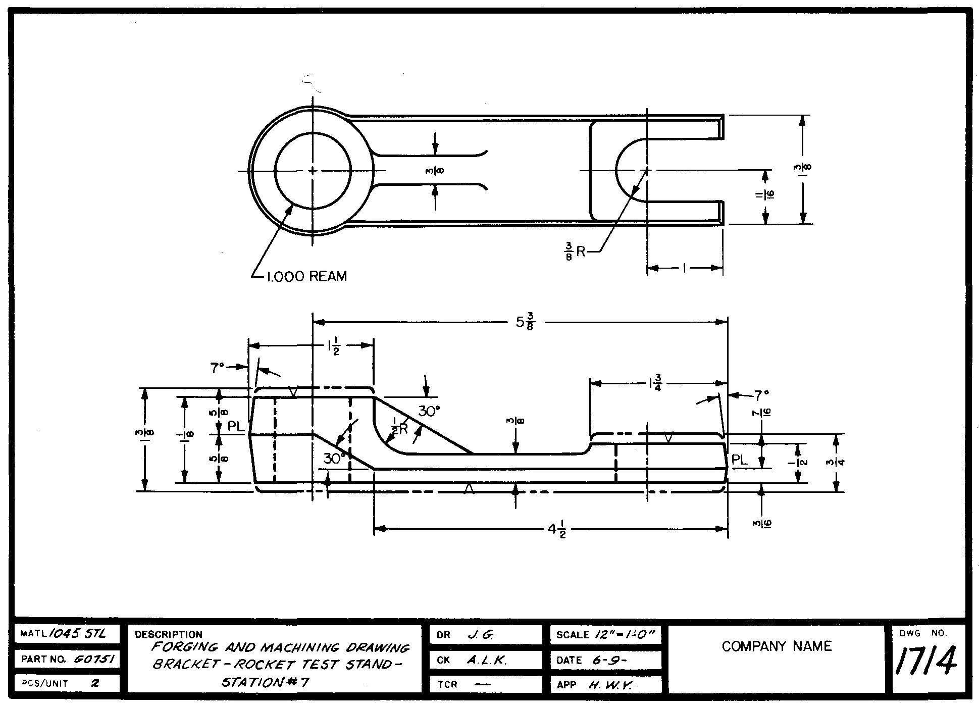
Such a drawing gives information for both the diemaker and the machinist. Let us consider some of the special features of a forging drawing which make it different from the usual working drawing.
Scale
In so far as possible, forging drawings should always be drawn full size.
Parting line
The parting line, Fig. 15-9, can be seen when the dies are mated together. It separates the upper and lower dies. The inner face of each die surrounding the impression is called the parting plane.
fig. 15-9. A parting line
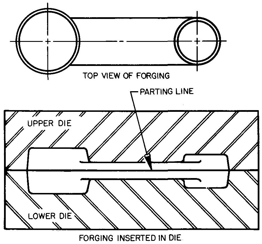
The position of the parting line depends upon the shape of the part. It may be located so that one half of the die contains all of the impression, depending upon the shape of the part. In this case the other half of the die would be flat with no impression. In other cases, the impression might be equally divided between the two die halves.
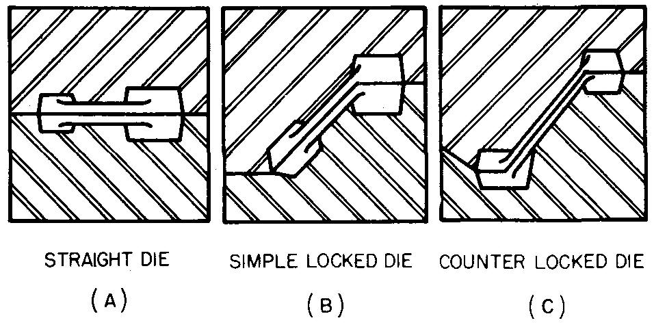
Figure 15-10 shows several positions for parting lines. Note that the parting line may extend along a straight line or it may be offset. The parting line should be indicated on the forging drawing as in Figs. 15-6 and 15-8.
fig. 15-10. Positions for parting lines
The symbol PL is placed at both ends of the line.
Draft
The slope or taper which must exist on all surfaces of a forged part so that it may be freely removed from the die is called the draft.
Draft is always shown and specified on forging drawings. The standard draft angle for outside surfaces varies from 5° to 7°, depending upon the shape of the forging. Inside surfaces should have a draft angle of 10°.
A method of dimensioning the draft angle is shown in Figs. 15-6 and 15-8. If the draft angle is the same for all surfaces of a forging, it may be given in a general note in or near the sheet title block.
Fillets and rounds
Fillets and rounds found on forged parts serve the same purposes as those on castings. They should be made as large as possible without interfering with the design of the part.
Sharp corners or small radii may produce defects in the forging and may reduce the life of the dies. No radii should be less than 1/8 inch.
Machining allowance
When only one drawing is prepared for a forged part, the amount of stock left on the forging for machining is indicated as in Fig. 15-8.
The outer lines, represented as alternate position lines, show how the forging will appear before machining. The solid lines indicate the final part after all the machining has been done. Finish symbols are always used to specify machined surfaces.
Powder metallurgy
Another method for forming metal parts to size and shape is the process of powder metallurgy. It should be noted that this process is often referred to as the pressed metal process. (This name should not be confused with pressing parts from metal sheets.)
It consists of compressing metal powders, either with or without the addition of nonmetallic powders, and heating them at high temperatures. The powder is squeezed into the required shape in a die by the pressure of a tool called a punch. The process of pressing powders into shape consists of first carefully blending the powders and mixing them in a tumbling machine.
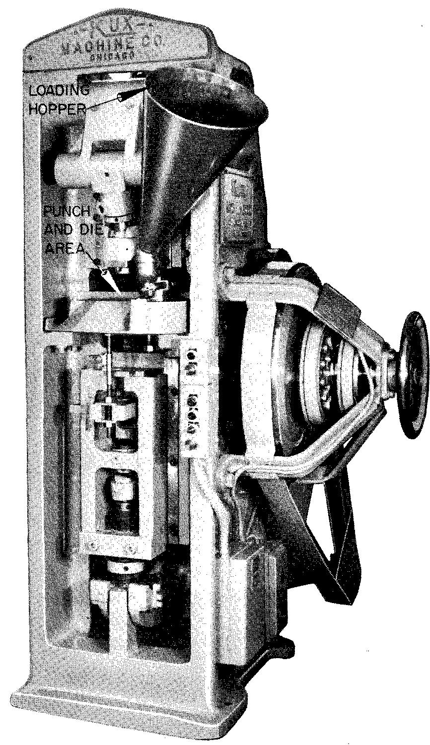
After being mixed, the powder is poured into small pails and then into a container called a hopper, on a press. The hopper permits the powder to flow down on to a moving platform or shoe, which, in turn deposits the correct amount of powder into the cavity of the die prior to each stroke of the punch.
The parts are then squeezed, or pressed, to shape by the force of the punch. The powder is compressed to approximately one-third of its original volume.
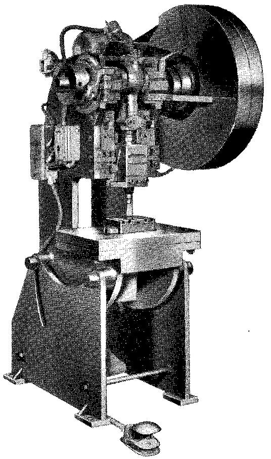
The press, Fig. 15-11, is capable of exerting pressures from 10 to 50 tons per square inch. It may be designed so the punch may push from the top only or from both the top and the bottom.
fig. 15-11. A powder metallurgy press
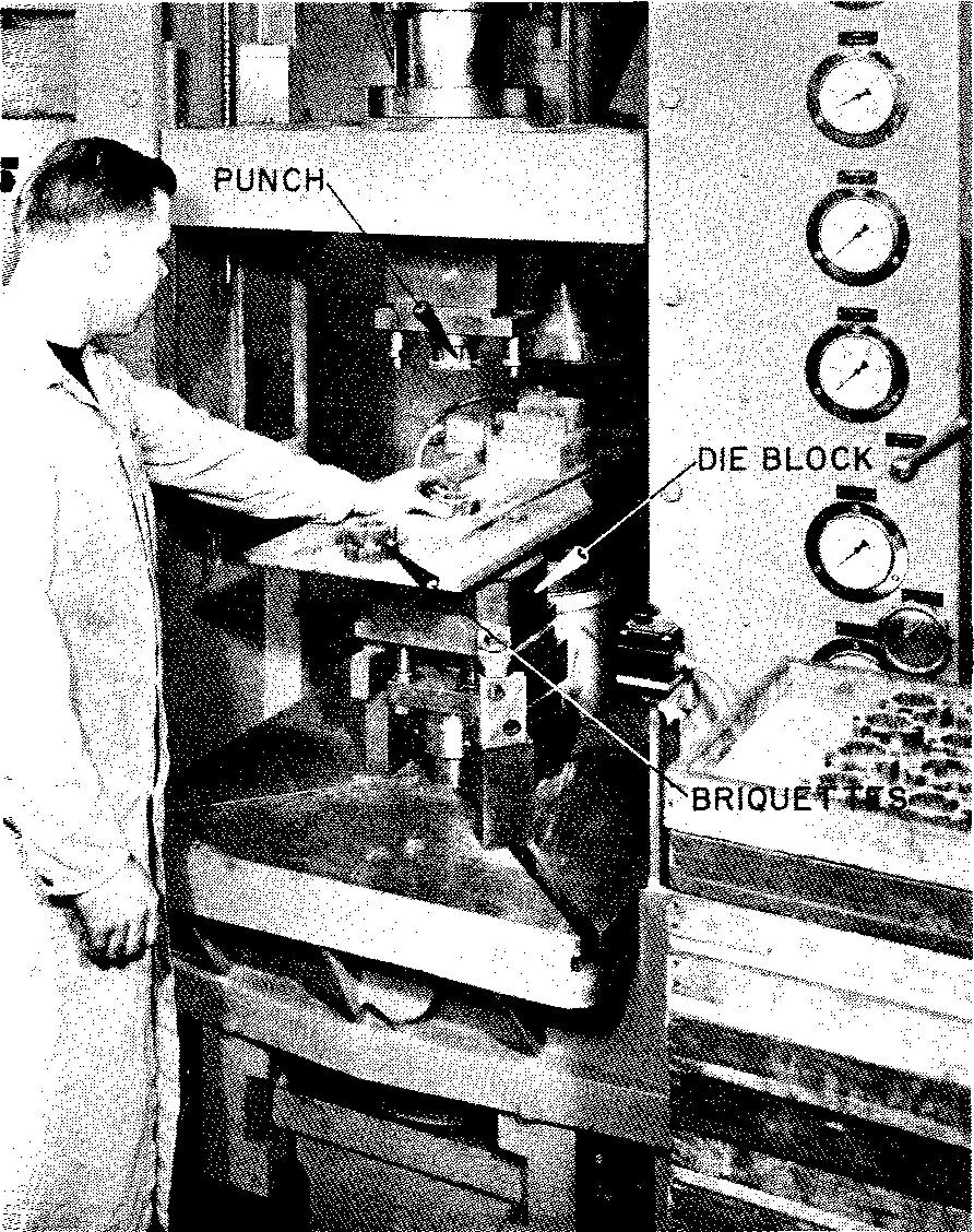
Parts may be pressed at the rate of as many as 30 a minute. The parts are mechanically ejected or lifted from the die. They must be carefully handled, since they are quite fragile and brittle. After pressing, the parts, shown in Fig. 15-12, are known as briquettes.
fig. 15-12. Briquettes
The briquettes are transferred to a furnace for sintering or baking. Except for any required machining, sizing, or tumbling operations, they are ready for use.
Steel objects were made some five thousand years ago by the Egyptians, who used a process similar to that which has been described. Iron ore was crushed into small particles and then hand forged to shape.
Powder metallurgy as we now know it was first successfully used in the production of machine parts in 1937. The success of the process was due, in large measure, to the perfected methods of producing metal powders and to the development of a controlled-atmosphere furnace.
Typical of the ingenuity of modern-day industry is the story of a method by which the metal powders for powder metallurgy are made.
Brass, bronze, nickel, silver, copper, and zinc powders are made by melting the metal and pouring it off in a thin liquid stream. A blast of steam, water, air, or other gas under high velocity is directed against the stream of molten metal. The stream of metal is actually blown into a powder form. The mixture is sifted through a fine screen, tested, and is then ready for use.
Parts to be made by the powder metallurgy process must be carefully designed specifically for this process. There are definite limitations which must be considered in the designing of the part and the dies.
Although most of these design considerations are beyond the scope of this text, they may be briefly summarized as follows:
1. Parts having threads and undercuts cannot be formed.
2. Thin sections of less than 1/8 inch and feather (extremely thin) edges cannot be formed.
3. Large and abrupt changes in size and shape must be avoided. Unlike liquid metal, powder will not flow around corners.
4. Spherical surfaces cannot be compressed.
5. Holes which are not parallel to the direction of the punch cannot be formed; that is, those which may be crosswise or at an angle to the punch.
Dies are designed by specially trained engineers and are made by highly skilled workers. They are usually made of tool steel and may be used to produce as many as 500,000 identical parts.
Dies made of carboloy or tungsten carbide have been known to produce over a million parts. Dies are made in one piece. Split, or two-piece, dies are not considered practical by powder metallurgical engineers. The punches are made from tool steel.
Pressed powder parts may be readily machined. In fact, it has been found that parts made by this process have better machining characteristics than metals of similar composition which have been cast. However, some metal compositions result in physical properties inferior to those made by other methods.
On the other hand, the process can result in the development of special mixtures impossible to produce by any other method.
The size of parts which may be produced by powder metals is limited largely by the size of the press.
As the size of the press increases, the speed at which it can operate is slower. It is generally understood that parts greater than 9 inches in diameter and 6 inches in thickness cannot be economically produced by the process of powder metallurgy.
There are many important advantages in making parts by this process.
1. Usually, only those surfaces of parts requiring extremely close tolerances need be machined. The excellent surface finish obtained is considered to be at least equal to, and in some cases superior to, that of a precision ground surface.
2. Powder metallurgy is a high-speed high-production process.
3. Iron and steel parts pressed to shape by this process may be hardened later.
4. Parts may be accurately produced. For example, when bushings are made by this process, tolerances of ±0.001 inch per inch may be obtained on the diameter and ±0.005 inch per inch on the length.
5. The surfaces of parts give better wear resistance, due to the excellent surface finish.
6. There is excellent uniformity (or evenness) of size for all parts.
7. There is little scrap or waste material.
8. A great variety of different kinds of materials for the same part may be produced by the same dies and punches.
9. Parts with sharp corners may be easily produced.
Powder metallurgy is considered comparatively low in cost for high quantity production. Studies have shown savings from 50 percent to 90 percent, depending upon the part, when compared to other methods of producing parts.
There is wide application of the use of parts made by this process, Fig. 15-13.
fig. 15-13. Parts produced by powder metallurgy
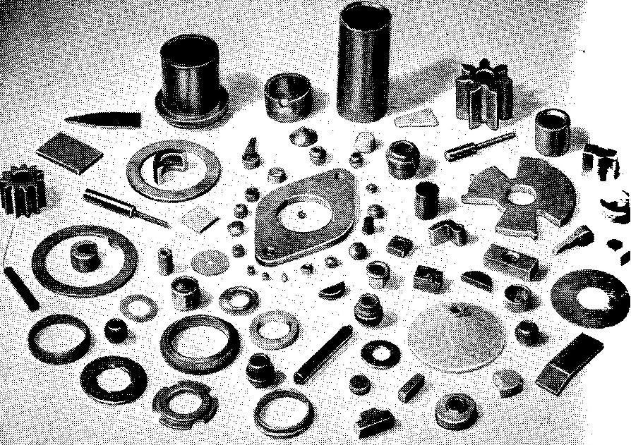
New possibilities in practically all fields are constant!} being developed in this rapidly expanding industry. Parts commonly made by this process are found in various household appliances, power tools, sporting goods, business machines, toys, and hardware and in countless other commercial and military uses.
Powder metallurgy drawing practices
Diemakers work from detail drawings of the machine part and therefore do not require a special drawing. Drawings of parts made by this process do not require any special techniques and are prepared in the same manner as those for parts which are machined from stock.
Pressed metal parts
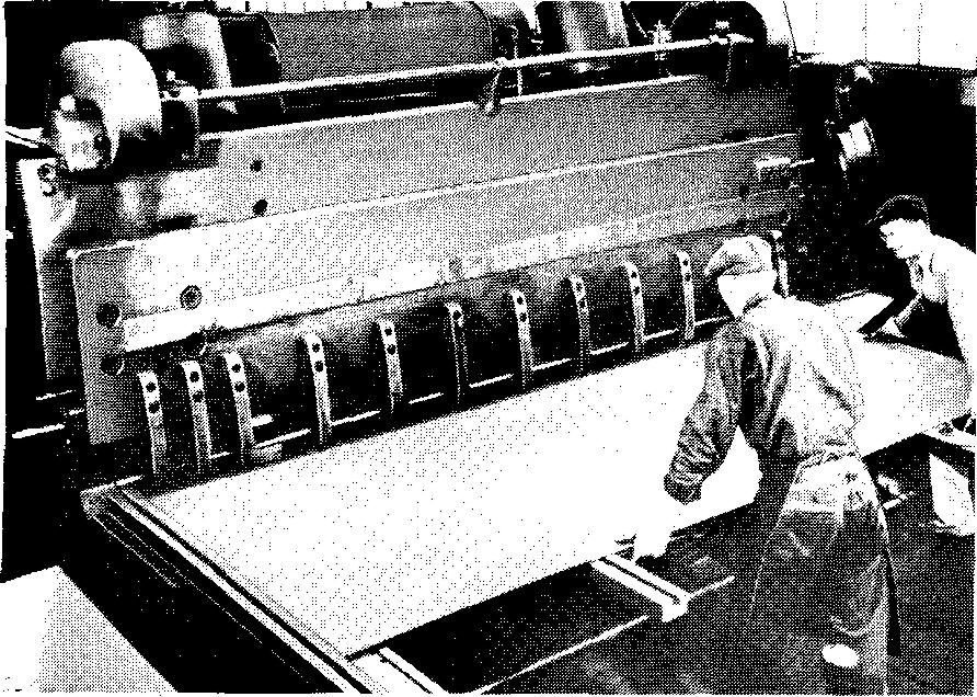
Machine tools which are used for pressed metals include giant mechanical or hydraulic shears and presses. Large metal sheets may be sheared to size and shape by one stroke of the shear, shown in Fig. 15-14.
fig. 15-14. A sheet-metal shear
The press brake, Fig. 15-15, is used to bend strips or sheets of metal.
fig. 15-15. A press brake
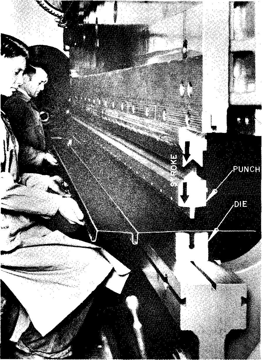
The press bends and pushes the metal into the final shape in a die under tremendous pressure. The die may be roughly compared to a mold which is used in sand casting.
Instead of molten metal being poured into the cavity of the mold, as in casting, a flat sheet of metal is forced by a punch into the cavity of the die under great pressure. The shape of the final part is determined by the shape of the punch and of the impression in the die.
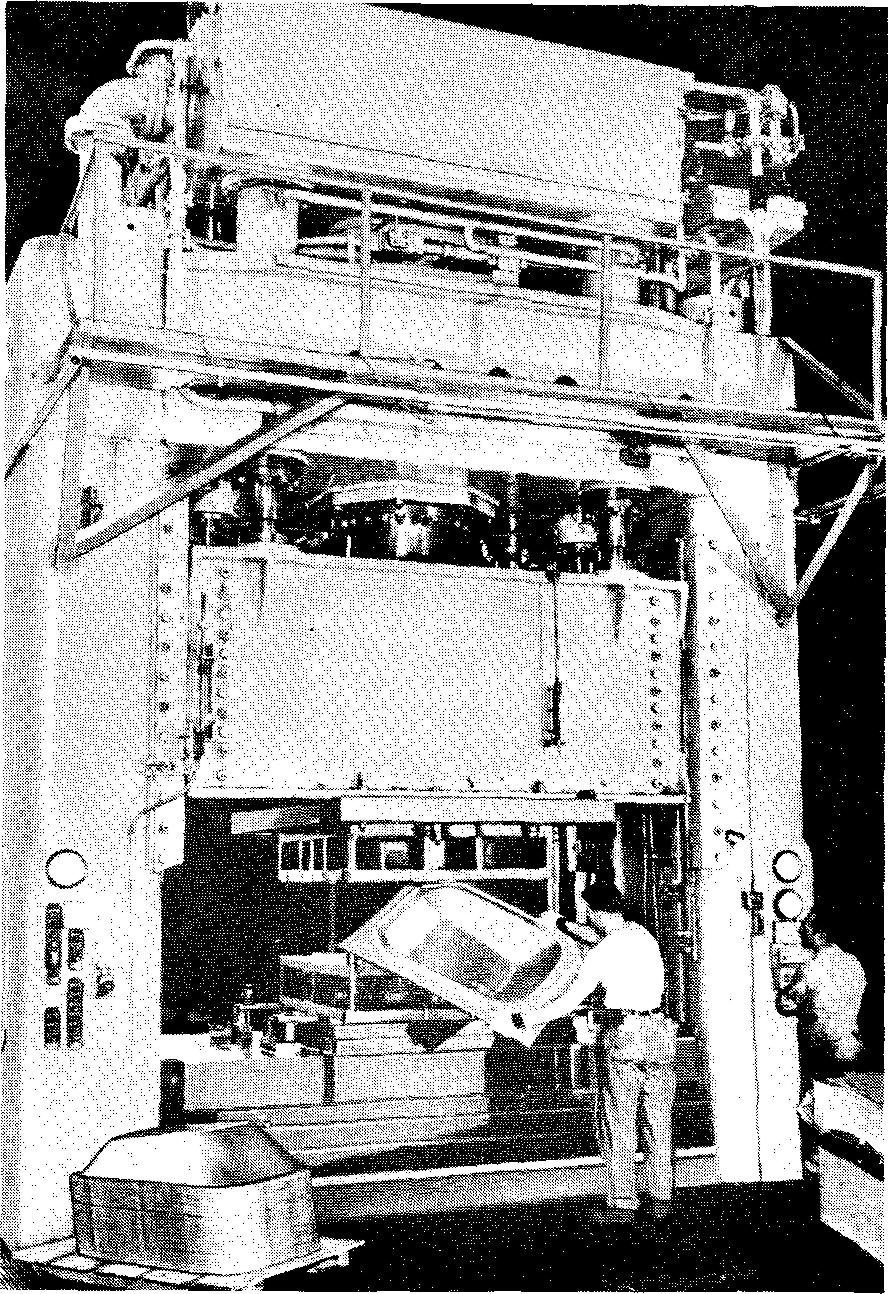
A giant hydraulic press is shown in Fig. 15-16.
fig. 15-16. A giant hydraulic press
Another machine tool used in metal forming is the punch press. This machine punches holes or openings of various shapes and sizes in metal sheets, shown in Figs. 15-17 and 12-7.
fig. 15-17. A punch press
Pressed metal drawing practices
As described the machines which form metal parts from metal strips and sheets require special dies and punches. The drawings for these dies and punches are prepared by highly skilled die designers and machine draftsmen. The drawings must be prepared to exacting standards.
Elements of design in this
highly complex field are considered beyond the scope of this text.
Machine
draftsmen are frequently required to prepare drawings of parts made by this
process. In this case, the parts are often drawn flat, or as they would appear
before bending.
Sheet-metal parts made by the pressed metal process are usually formed entirely by mechanical means. That is, the part is usually stamped to size from a flat sheet and is then mechanically bent to the required shape. Pressed metal parts require little further machining after sharp corners are removed.
Thin metal parts made by methods other than pressing or punching are discussed in section 16.
Notation for holes on parts made by pressure
The notation for a hole on parts which are produced by pressure would read, for example, 7/8 DIA, or, if a tolerance is required 1.500/1.505 DIA.
Notation for holes which: are further enlarged or which are entirely produced by shop operations should specify the hole diameter followed by the word DRILL REAM, PUNCH, BROACH, BORE, and so on.
Review questions
1. List some of the more commonly used metals in forging.
2. Explain why forged parts are said to be less porous and stronger than parts produced by casting.
3. Briefly describe the process of open die forging.
4. Briefly describe the process of closed die forging.
5. Briefly describe the press forging method.
6. How do the forging dies determine the final shape of the part?
7. How do forging drawings and machining drawings differ in their use?
8. Explain what is meant by a parting line. What symbol is used on the drawing to identify this line?
9. How would you compare the purpose of draft as used in forging to draft as used in the casting process?
10. How is the machining allowance indicated on a forging drawing?
11. How are finished surfaces specified on a forging drawing?
12. Prepare a brief outline to describe the process of powder metallurgy.
13. When was this process first successfully used in the production of machine parts in the United States?
14. What factor limits the size of the parts which may be produced by this process?
15. List some of the advantages of this process.
16. Are specially prepared drawings necessary for this process? Explain.
17. Describe the use of a press brake.
18. What operations are punch presses capable of producing?

![]()