Forming parts by casting
Introduction
Casting is a process of forming parts to rough size and to the desired shape by pouring molten metal into hollow molds. There are many ways of casting metal parts.
In most plants the selection of the best method of casting a particular part is the responsibility of the design engineer. Such factors must be considered as the size, weight, strength, and the required accuracy of the features of the part.
Also, the shape of the part, the intended use of the part, and, of course, the comparative costs of the various processes must be considered.
It is important for the machine draftsman to learn as much as possible about the general practices of casting metals. The method by which a part is cast usually determines how the part should be drawn, dimensioned, and specified.
Four basic casting methods, sand casting, die casting, precision investment casting, and permanent mold casting, are explained in this section A more complete study of casting processes will be found in text and reference books dealing with casting practices. The student will find these interesting and instructive.
Casting is an ancient art dating back many centuries. A great deal has been written about the early methods of sculpturing and casting, and the student will find additional reading on the topics to be particularly interesting.
Sand casting
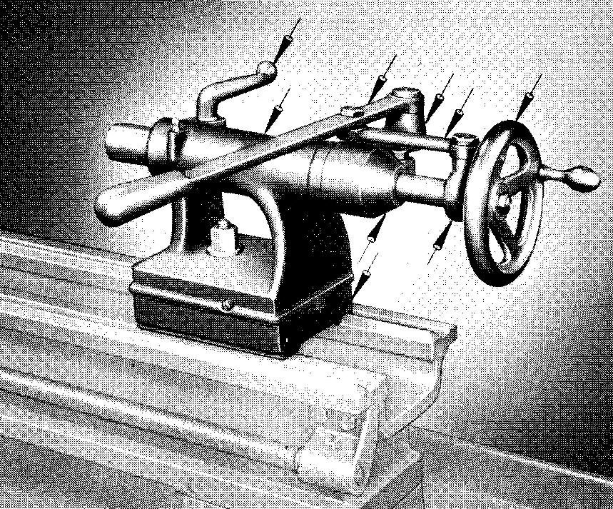
Parts which are produced by pouring molten metal into a sand mold are called sand castings. Examples of such parts are shown in Fig. 14-1.
Fig. 14-1. Arrows denote parts produced by sand casting

The process of forming the mold cavity is referred to as molding. The mold is made by ramming specially prepared sand around a wood or metal model or pattern of the part.
The pattern is carefully removed from the mold without disturbing the sand. Molten metal is then poured into the hollow impression or mold. When the molten metal has solidified, the part, or casting, is removed from the mold.
This general process is described in greater detail below. This is the simplest and most widely used method of forming metals or alloys into the desired shape.
Castings are made from iron, steel, aluminum, brass, bronze, copper, magnesium, and from most other metals and alloys.
Castings may range in size from parts weighing a few ounces to those 10 tons or greater. Castings are usually made for parts with complex shapes, or those parts which would be difficult, and in many cases impossible, to cut to size and shape from solid stock by machines.
When the drawing specifies that a part is to be formed by casting, a wood pattern is first made. Wood patterns may be made for one casting or for a part which will be cast several thousand times.
The patternmaker must closely examine the drawing so that he may determine the proper shrinkage allowance, the machining allowance, the position for the parting line, the draft, and the type of pattern required. These terms will be explained in the following paragraphs.
Shrinkage allowance
The casting will measure slightly smaller in size than the pattern used in the mold, since practically all metals shrink when they are cooled. The amount of shrinkage varies with different metals.
Cast iron, for example, shrinks about 1/8 inch per foot while cast steel shrinks as much as 1/4 inch per foot. To allow for shrinkage, the patternmaker must make the pattern oversize.
Instead of continually adding the amount of shrinkage to each dimension taken from the drawing as he makes the wood pattern, he uses a special, rule known as a shrink rule.
Different shrink rules are used for different metals and alloys. Each division of the rule is made correspondingly larger than that on a regular rule.
As each measurement is made, the proper shrinkage allowance is continuously added by using the shrink rule. The drawing indicates the kind of metal which is to be cast.
Shrinkage allowance is not specified on the drawing.
Machining allowance
Parts which have been made by the sand-casting process have rough surfaces which for many uses must be finished by machining.
When a finished surface is required, additional stock is added to the pattern, making the casting larger wherever the allowance has been added. This increase in the size of the casting is called the machining allowance.
Although the allowance is usually 1/8 inch, it may vary with the size of the casting, the type of machining operation necessary, and the metal from which the casting is to be made. Machining allowances are not specified on the drawing.
The patternmaker is guided solely by the finish symbols placed on the drawing, which represent the surfaces which must be machined. Thus, the pattern is made larger wherever a finish symbol is placed.
Parting line
Sand for the mold is held in place in a box called a flask. The flask is made in two parts. The upper part is called the cope and the lower part is called the drag. Figure 14-2 shows a sectional view through a flask.
Fig. 14-2. A section through a flask
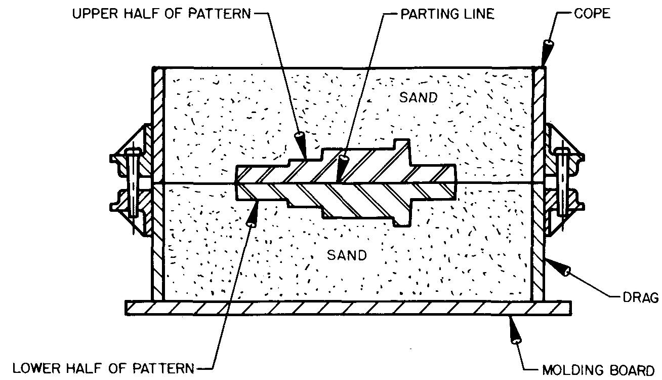
The pattern is inserted, and sand is firmly packed and rammed around it. Thus the pattern is completely surrounded by sand.
The pattern must be carefully designed. It must be constructed so it can be removed or drawn from the sand from both the cope and the drag without destroying the impression.
Except for very simple parts, most patterns are made up of two or more pieces. Usually one half makes an impression in the cope, and the other half makes an impression in the drag. The line separating these pieces is called the parting line.
The patternmaker decides where the parting line should be located on the pattern. Specifications for the parting line are omitted on the drawing.
Draft
The amount of taper or slope away from a line perpendicular to the parting line is called the draft. Draft, shown in Fig. 14-3, is produced on the pattern to assist the molder in removing the pattern from the sand mold, eliminating the need for excessive rapping or striking.
Fig. 14-3. A split pattern
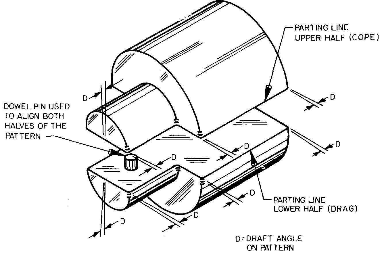
Striking the pattern with any force would tend to destroy the impression in the sand. It might also injure the pattern. Generally, wood patterns require a draft of 1/8 inch per foot, or not less than 1° or 2°. Draft is usually not specified on the drawing.
Types of patterns
The shape of a part and the expected difficulty in removing the pattern from the mold determine the type of pattern required. Patterns may consist of one, two, or more pieces.
By custom of long standing, the patternmaker makes all decisions concerning the type of pattern. The patternmaker also makes the decisions concerning any details of pattern construction.
Therefore such details are not specified on the drawing. However, the patternmaker must ensure that the part will meet the specifications.
Cored holes and openings
Some parts, such as the one shown in Fig. 14-4, contain large holes or hollow portions. Cores are used to prevent molten metal from filling in the desired openings in the mold.
Fig. 14-4. A part which requires a core
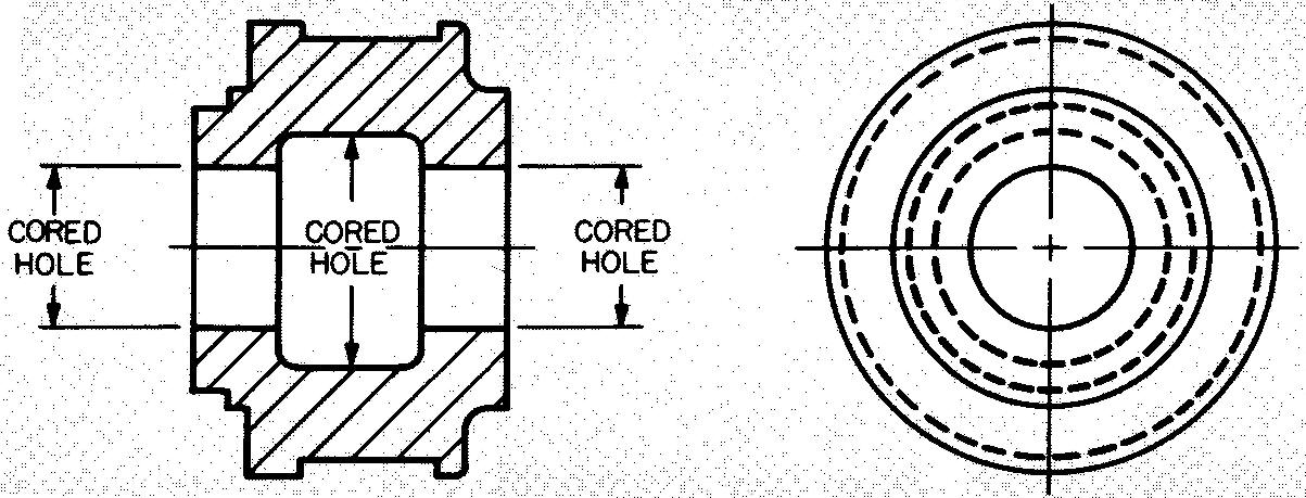
Cores are made by ramming a special mixture of sand and a bonding agent into a wood or metal corebox which contains a mold of the same shape as the opening. The core is removed from the box and is baked to produce a firm but brittle material.
Figure 14-5 shows a corebox and core. In this case a half core-box is made, since both halves of the core are identical. The two halves are joined together.
Fig. 14-5. Corebox and core half
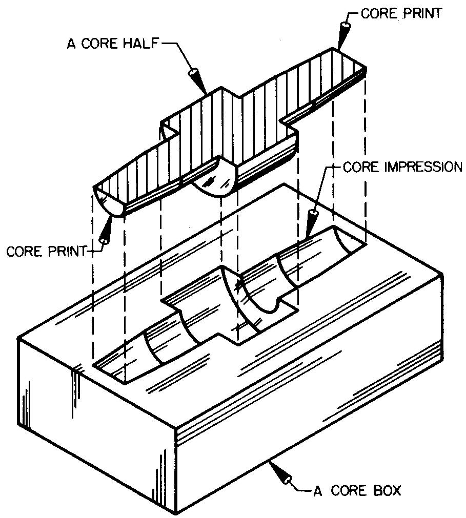
Core prints are added to both the core and the pattern to hold the core in the proper position in the sand mold. Core prints extending off the ends of the pattern form a cavity in the sand.
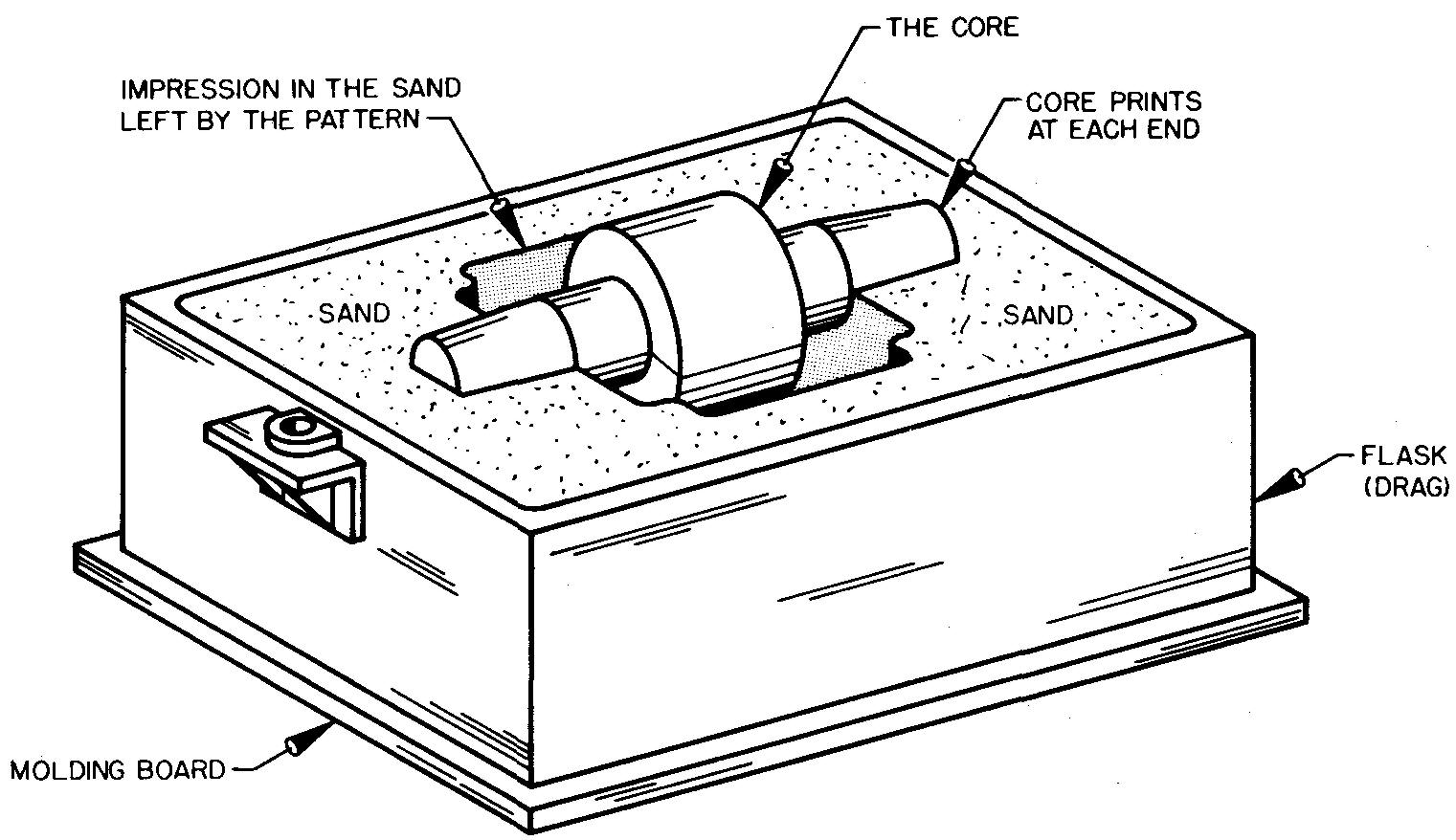
Mating core prints on the ends of the core rest in these cavities, holding the core in place, as shown in Fig. 14-6. Only that part of the core which corresponds to the opening is allowed to project into the mold.
Fig. 14-6. Mold with full core in position
The metal is poured into the impression left by the pattern through a hole in the sand called a sprue, shown in Fig. 14-7.
Fig. 14-7. Section through a flask (core in position)
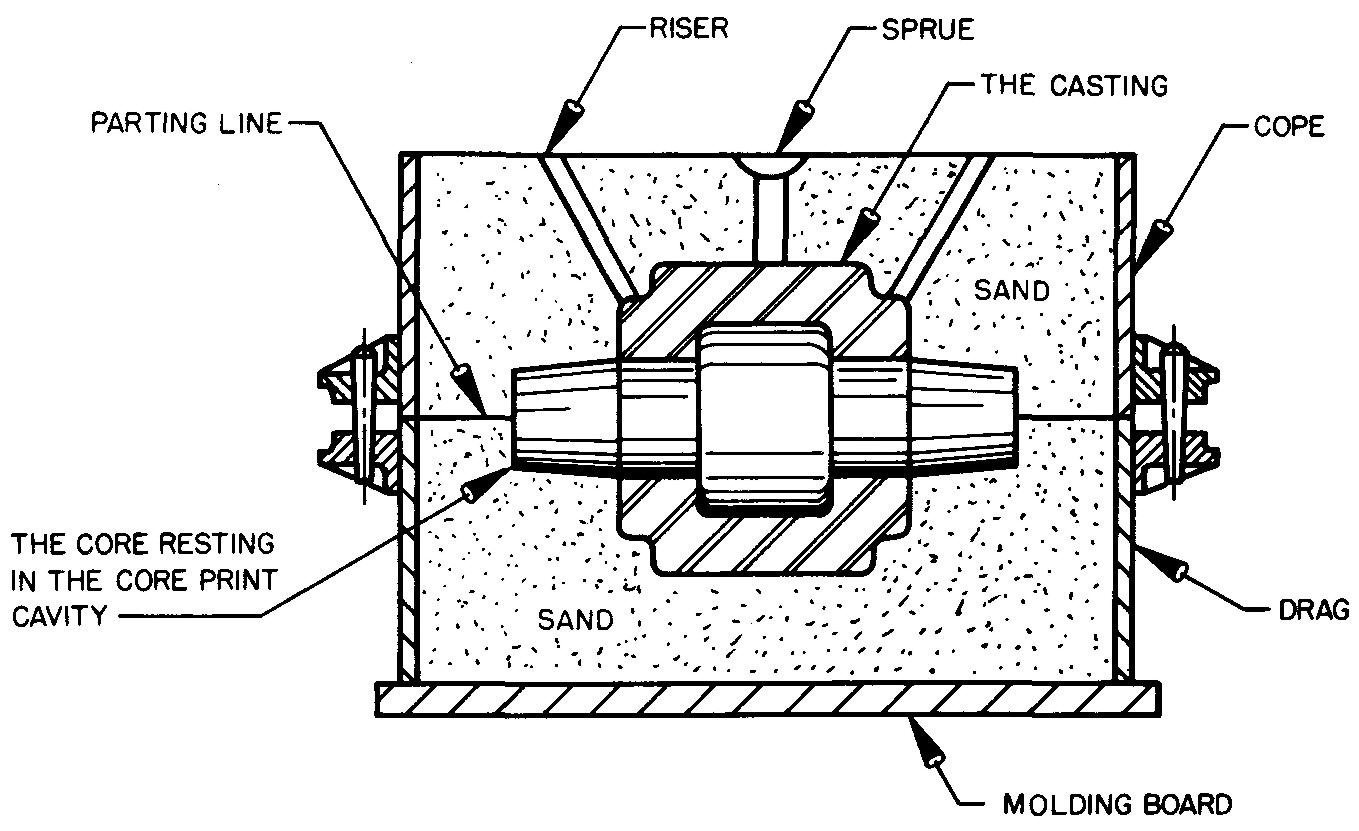
The sprue is made by the molder. Since the core remains in the mold, the molten metal must flow around the core, filling in the space left by the impression of the pattern. Gases are permitted to escape through the porous sand and through holes called risers which are also made in the sand by the molder.
When the casting has cooled and solidified, it is removed from the sand. The sand core, if not already disintegrated by the heat, is then broken away, which leaves the desired opening in the casting.
Generally, small holes are not cored, since they may be more easily produced by drilling from the solid casting. Large holes are frequently cored and then are later bored to a precise size.
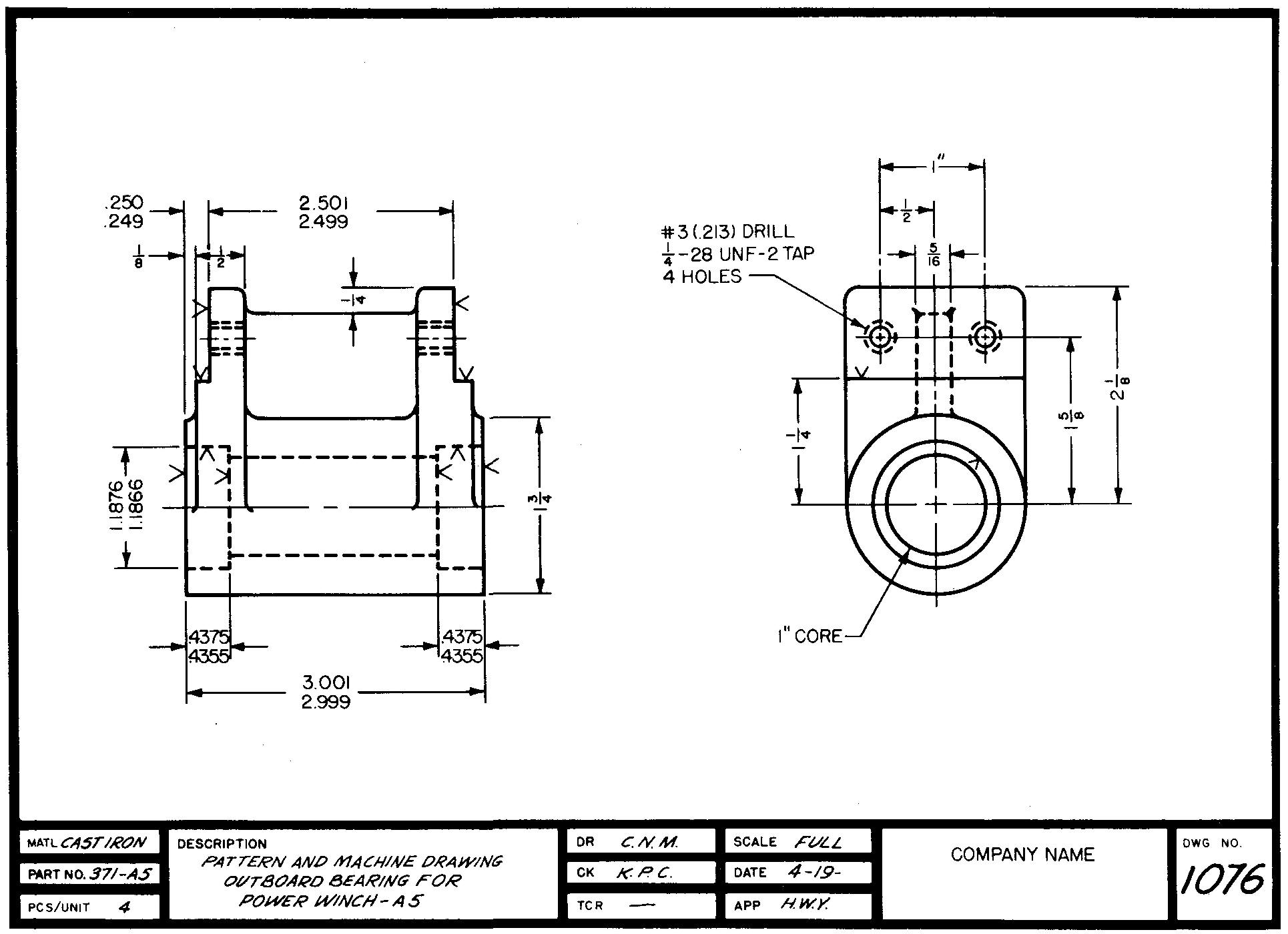
Cored holes are specified on the drawing as shown in Fig. 14-8.
Fig. 14-8. Combined pattern and machining drawing
Drawing practices for sand castings
Industrial practices vary somewhat as to how casting drawings should be made. One of two different methods may be used. The most common method is to prepare one drawing, Fig. 14-8, which serves both the patternmaker and the machinist.
Fig. 14-8. Combined pattern and machining drawing
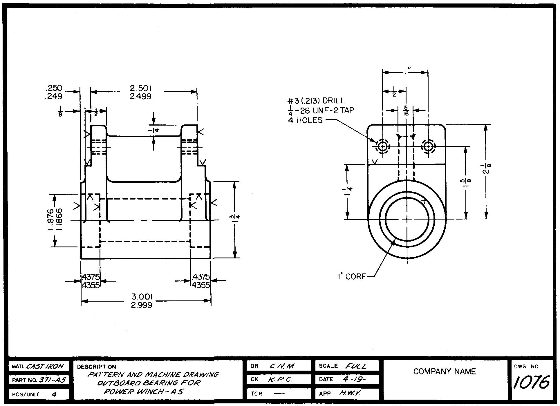
Another method, used in some industries, is to prepare two separate drawings of the part: one drawing for the patternmaker, Fig. 14-9, and one for the machinist, Fig. 14-10.
Fig. 14-9. A pattern drawing
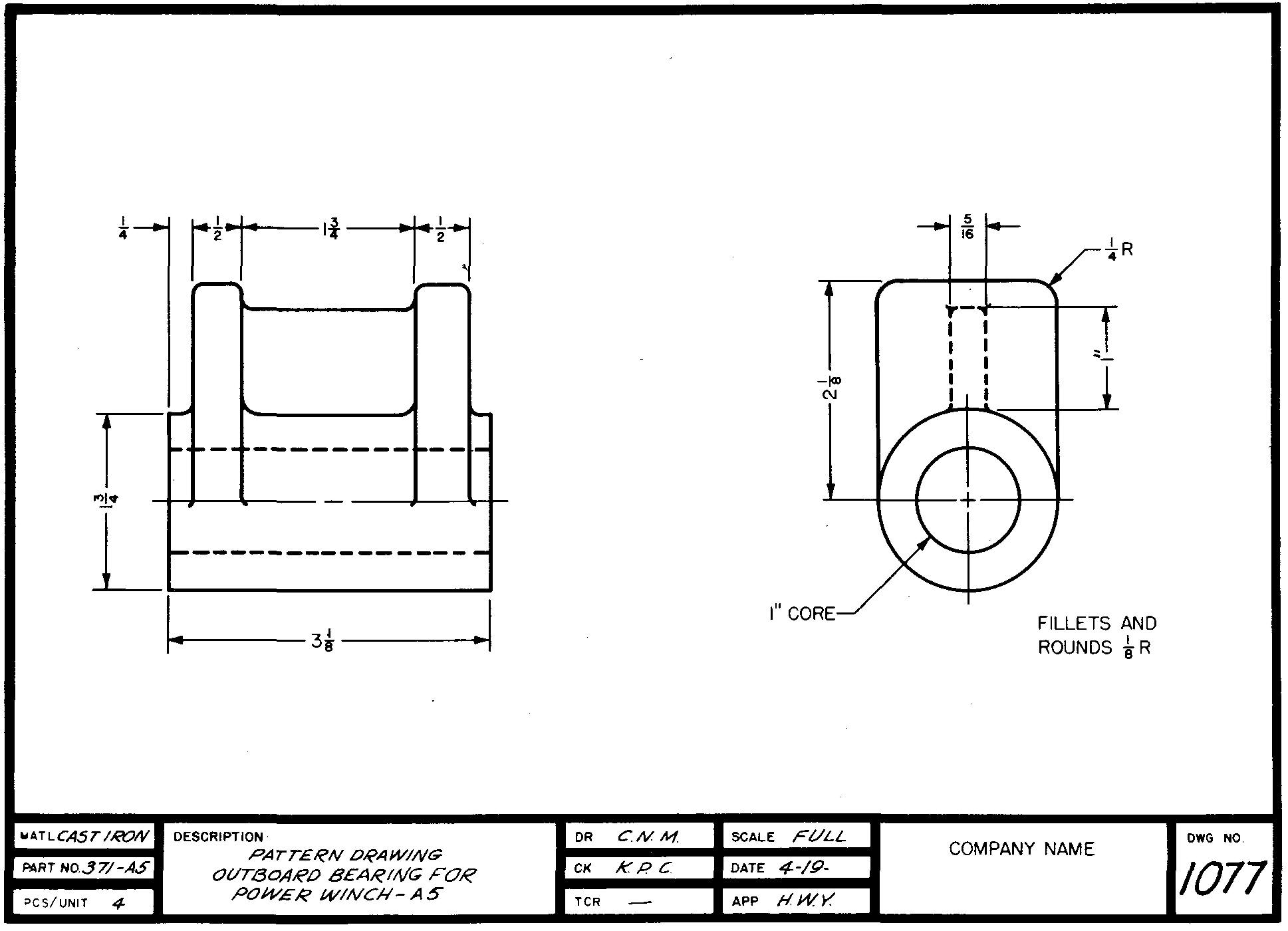
Fig. 14-10. A machining drawing
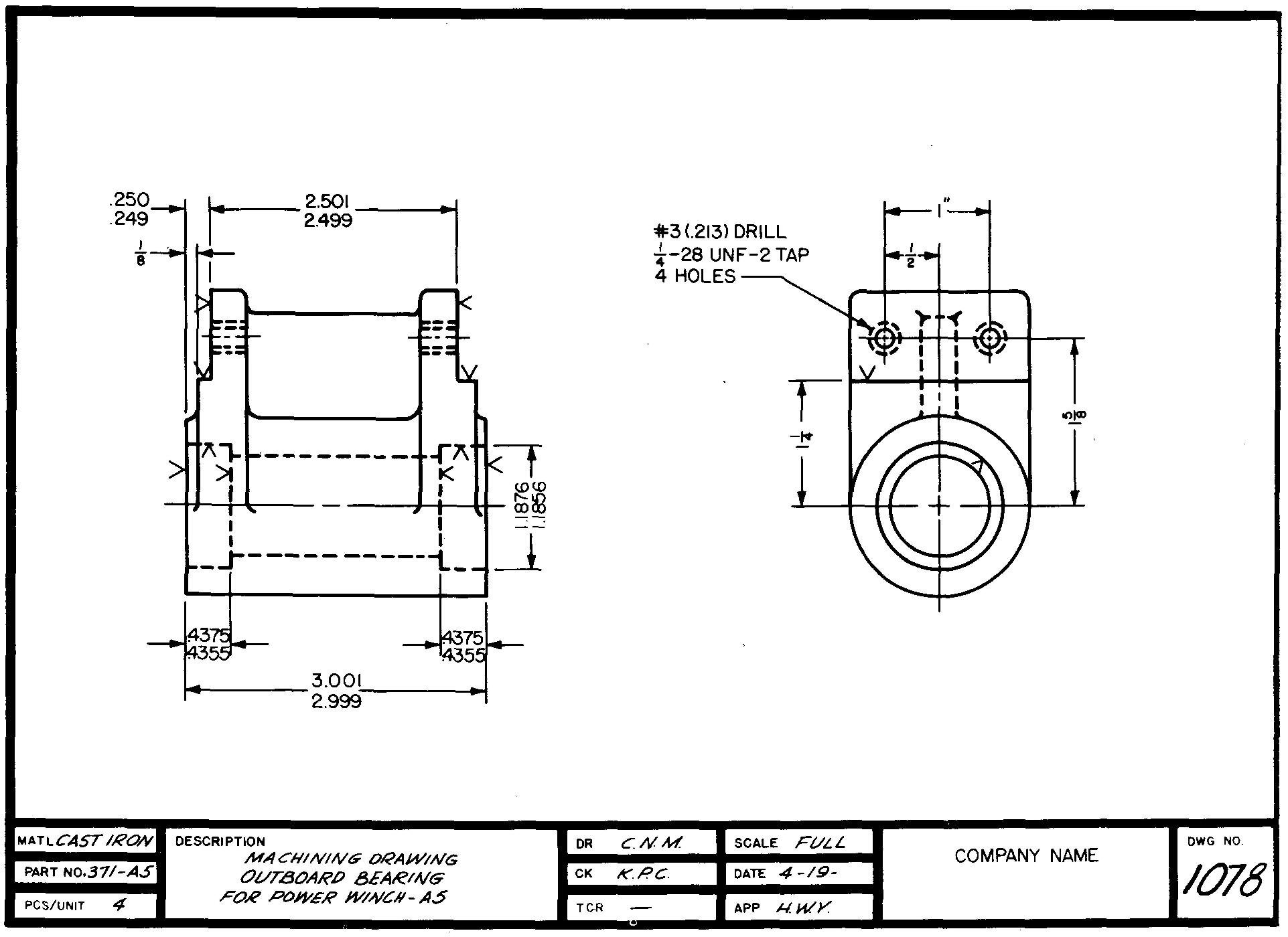
Two separate drawings are often prepared for unusually complicated parts. For purposes of illustration a reasonably simple part has been shown in Figs. 14-8 through 14-10.
Most companies have developed their own standards which apply to casting-drawing practices. It is the responsibility of the machine draftsman to check these practices carefully when making detail drawings of castings.
Dimensions and notes
Avoid using dimensions which direct the patternmaker to work more closely to size than the nearest 1/16 inch. Machining dimensions may be as precise as necessary.
The notation for a hole which is produced to final size by casting would read, for example, 3/4 DIA.
Notation for holes in castings which require further enlargement or those which are entirely produced by shop operations should specify the hole diameter followed by the word DRILL, REAM, BROACH, BORE, and so on.
Die casting
The process of forcing molten metal under high pressure into metal molds or dies is called die casting.
Printing type was first successfully cast by machine methods in 1838. By 1885, the linotype machine had made type casting even more mechanical. It has been said that these typecasting processes gave rise to die casting as we now know it.
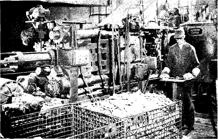
A die-casting machine is shown in Fig. 14-11 A.
Fig. 14-11. A die-casting machine
A
B
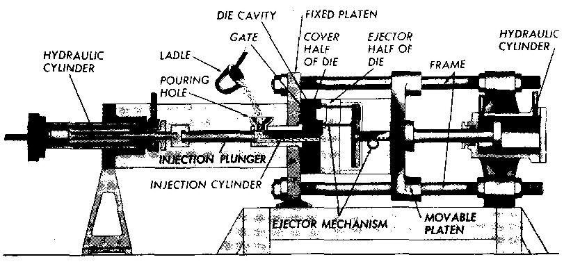
It can be operated by relatively unskilled workers. The machine melts and forces the metal into molds, allows time for the metal to solidify, and then mechanically opens the molds and ejects the finished castings. The operating parts of a die-casting machine are indicated in Fig. 14-11B.
Parts made by die casting are especially designed for this particular process. There are definite limitations governing parts which can or cannot be produced by die casting.
Design requirements are not discussed in this text, but it must be understood by the machine draftsman that considerable engineering attention is required for all features of die-cast parts. The selecting of the proper design would, of course, take place prior to making the detail drawings of the parts.
Dies are designed by highly trained engineers and are made to exacting standards. Designing and building dies is usually very time-consuming and expensive.
The process of die casting is considered expensive for limited production of parts but is economical for producing large quantities of parts.
An important advantage is that the final castings require little or no machining. In fact, excessive machining is undesirable.
A reduction in the strength of the part may result from cutting through the chilled surface skin produced by the die-casting process.
Parts made by die casting have other important advantages. The castings have an excellent surface finish. Relatively thin and uniform sections may be cast, permitting great savings in cost due to less metal used.
Tin alloys, for example, may be cast with sections as thin as 1/32 inch.
Dies are frequently designed with several cavities which permit the molding of several parts at once.
Die castings may be made to extremely close tolerances. Tolerances as small as from =0.001 inch to ±0.002 inch per inch can be maintained. Die castings can faithfully reproduce extremely fine detail.
As an example, it is possible to cast exterior and interior threads as fine as 24 threads per inch.
Gear teeth may also be cast. Die casting threads enables the faster production of many parts because it eliminates the process of cutting threads on a lathe or of using a tap and die stock.
Die casting is best suited for metals having low melting points. These include zinc and zinc alloys, aluminum, lead, magnesium, and tin. Iron and steel, for instance, cannot be die cast.
Because of the cost of the dies and of the machinery, the quantity of parts made by this process must be quite high to make die casting economical.
Small parts such as zippers and business machine parts may be made at the rate of several hundred a minute.
Figure 14-12 illustrates a wide range of parts which may be made by the die-casting process.
Fig. 14-12. Parts produced by die casting
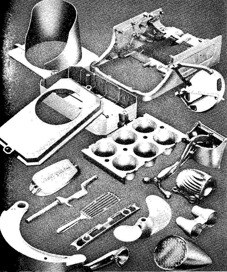
Other parts include decorative trimmings, handles, carburetor parts for automobiles, parts for electrical appliances, various machine parts, toys, models, trophies, and parts for vending machines, pencil sharpeners, surgical apparatus, and fire extinguishers.
Drawings of die castings show the final part with all the necessary machining symbols, specifications, and dimensions. Both the die-maker and the machinist use the same drawings.
There are no special or unusual drawing requirements for die-cast parts. There is little need for a great amount of machining on die-cast parts except in special cases when the cutting of holes and threads and the finishing of a particular surface may be necessary.
Thus, the die maker will be the principal user of the drawing.
Precision investment casting
This process, also called lost wax casting, is a method of casting parts to an accurate size and with a smooth surface finish.
The first step involves the making of a die.
The cavity of the die may be machined to size and shape, or it may be cast by using a master pattern which is identical to the final part. The dies are usually made with several impressions of the same part.
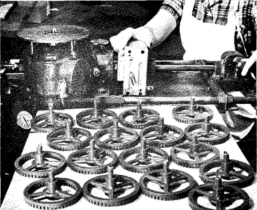
The die halves are then locked together and a liquid wax is poured under pressure into the cavities. Wax patterns for large castings, Fig. 14-13, are produced by using a high-pressure wax pump.
Fig. 14-13. Large wax patterns
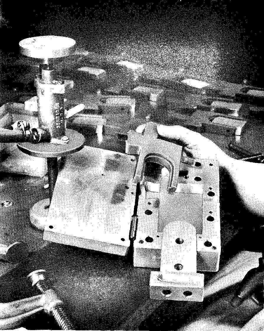
The dies are separated and the wax patterns are carefully removed as shown in Fig. 14-14.
Fig. 14-14. Removing the wax pattern from the die
Wax runners, called sprues, are next formed. These join several wax patterns together. The joined patterns are placed in a metal container to which wet plaster slurry or a sand mixture called the investment is added, as shown in Fig. 14-15. (To invest means to envelop.)
Fig. 14-15. Adding the investment
(A) flask placed around sprue prior to pouring of the investment slurry
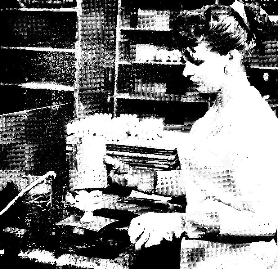
(B) the sprue tree is placed in an open metal flask
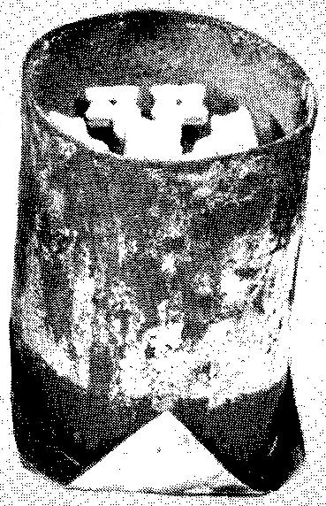
(C) the investment slurry is poured into the flask
The flask, with its contents of wax patterns surrounded by the investment mixture, is next placed on a vibrating machine which firmly packs the mixture around the patterns.
The mold is then placed in an oven, Fig. 14-16, and is baked from 4 to 12 hours for wax elimination. During the baking, the wax pattern melts and runs out. (In spite of the term lost wax, the wax is really not lost, since the wax is recovered and may be used again.)
Fig. 14-16. Loading an automatic oven for wax elimination. This is where the wax is lost
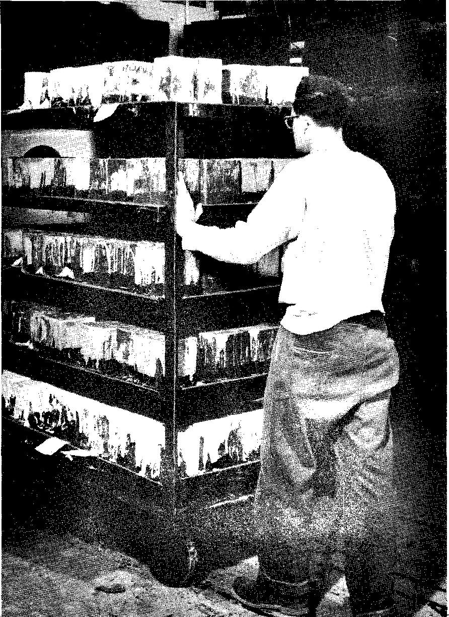
The mold now consists of a block of investment material containing cavities which are identical in shape to the wax pattern.
These molds are heated in a curing furnace and are removed as shown in Fig. 14-17.
Fig. 14-17. Removing the heated molds from a curing furnace
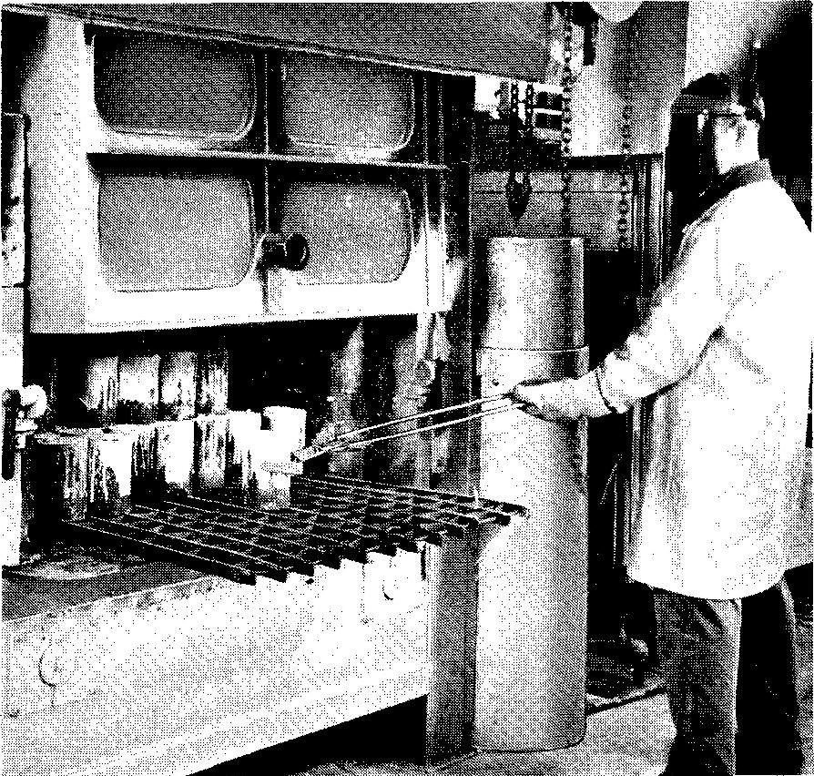
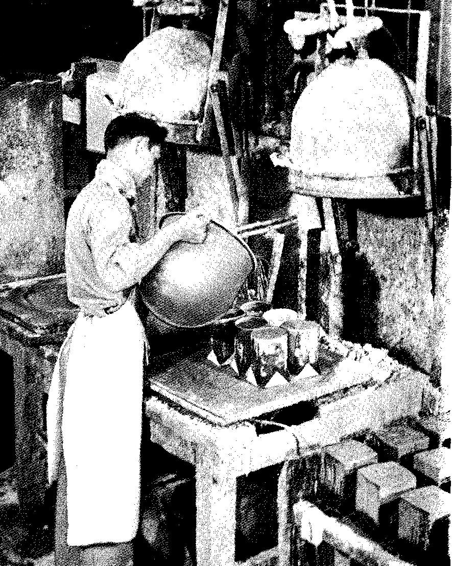
The cavities are then filled with molten metal, Fig. 14-18.
Fig. 14-18. Pouring metal into the mold
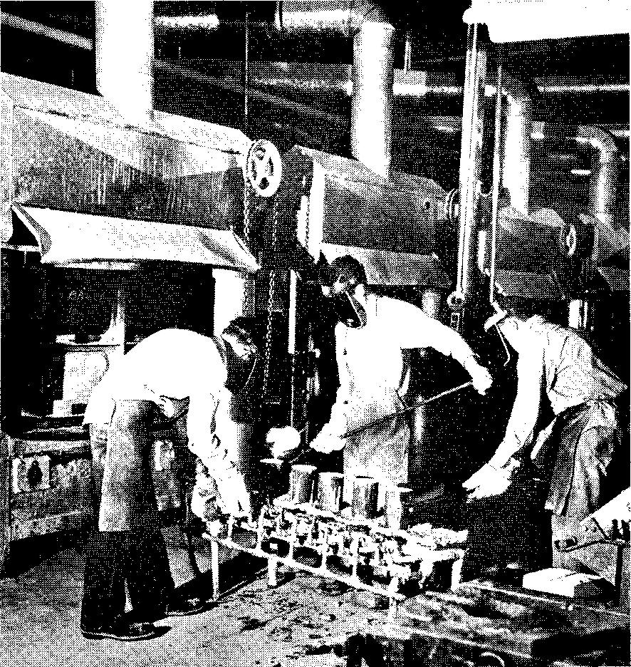
When the mold has cooled, the investment material is broken away and the finished casting is removed.
Wax was used for molding metals as early as Fourteenth Century Italy. Medals, medallions, and even statues were cast in molds formed by wax patterns. This ancient process received little attention until the second decade of this century, when it was adapted for dental work.
The jewelry industry began to use the process in the early thirties.
During the early stages of World War II, the lost wax process was carefully studied and adapted for the production of small turbine blades and other complex parts for both commercial and military use. The process has rapidly advanced to the point where it now is an important method used for making a wide variety of parts.
Parts commonly made by this process include turbine and compressor blades, turning vanes for jet aircraft, parts for cloth cutting machines, motion picture projectors, postage meters, binoculars, conveyor links, rock drills, and aircraft, automotive, and diesel engines.
There are many advantages to be gained from precision investment casting. A fine surface finish and close casting tolerances (from ±0.003 inch to ±0.005 inch per inch) may be obtained.
Extremely complex shapes may be cast. Any alloy which may be cast by other methods may be used in this process. In fact, many alloys which formerly could only be machined with great difficulty and expense may now be cast.
The process also has its limitations. Engineering costs are usually high due to increased design time. Skilled workers are required to make the molds and dies.
The process can be used to make parts weighing no more than an upper limit of roughly 35 pounds. In spite of these limitations, parts made by this process are being used more and more in practically all kinds of industries.
As in the die-casting process, there are no unusual drafting practices required for the machine drawing.
However, it should be noted that, because of the high degree of accuracy and the superior surface finish obtainable by this process, little, if any, machining should be necessary. The drawings are used largely by the patternmaker and diemaker. Only in special cases does the machinist use the drawings.
Permanent mold casting
This type of casting differs from sand casting in that the mold is made of metal and the preparation of the mold requires no pattern. The mold cavity is machined from a block of cast iron or steel.
As in sand casting, the mold consists of two halves. Cores made from steel or sand are used where necessary, much in the same way as for sand casting.
Parts made by this process have several advantages over those made by sand casting. The quality of metal is better, the parts have a better surface appearance, and a higher degree of accuracy can be obtained.
In some cases, depending upon the simplicity of the part, permanent mold castings are less costly to produce than those made by other methods.
Castings made in metal molds can generally be used without machining except for certain features of the part which may require more accuracy than it is possible to produce by casting. Tests prove that castings made by this method are from 10 to 20 percent stronger than sand castings.
The increased strength and superior surface finish are brought about by the chilling action of the metal mold upon the molten metal as the latter is poured into the mold.
Parts which have complex shapes are difficult to produce by this process. It is important to remember that the mold must be prepared by machining.
While modern industrial processes have few limitations, unusual machining operations often take large amounts of time and are therefore unusually expensive. Other methods of manufacture are often substituted for the permanent mold process when costs in producing parts are unduly high.
In our study of sand casting, it was noted that the casting could be easily removed from the mold by simply breaking away the sand from around it. This is not the case for permanent mold castings.
In this process, the poured casting in the cavity is surrounded by solid metal. Special attention to the mold design is required, in order to reduce the problem of removing the casting from the two halves of the mold.
Draft allowance, for example, must be made from 3° to 5°. The process frequently results in somewhat higher labor costs in the design and manufacture of the molds.
Parts molded in this manner usually range in size from a few ounces to 20 pounds, although parts weighing as much as 500 pounds have been successfully cast. A metal mold may be used for as many as several thousand shots or pours. There is a case on record where one mold was used to pour 100,000 castings.
The production rate depends upon how complex the part is. Engineers have set the rate as "higher than sand casting, but somewhat less than die casting."
While the accuracy which may be obtained by this process depends upon the size and complexity of the parts, tolerances of ±0.002 inch may be readily obtained for most small castings.
Finish or machining allowances of from 1/32 inch to 1/16 inch are usually sufficient, compared to a machining allowance of 1/8 inch for sand castings.
The thinnest section recommended for a part made by the permanent mold process is 1/8 inch, although sections as thin as 1/10 inch are possible on some parts.
Materials commonly used for casting parts in metal molds include lead, tin, zinc, aluminum, magnesium, and brass. The process has been perfected to the point where alloy steels may be cast for jet engine parts.
Other commercial and military applications of parts produced by the permanent mold process include many cylindrical bushings, liners, and valve seats for the oil, chemical, paper and pulp, and textile industries.
Parts for household electrical appliances, outboard motors, and automobile and aircraft engine parts are also produced by this process. Figure 14-19 shows several parts which were made by the permanent mold process.
Fig. 14-19. Parts produced by the permanent mold process
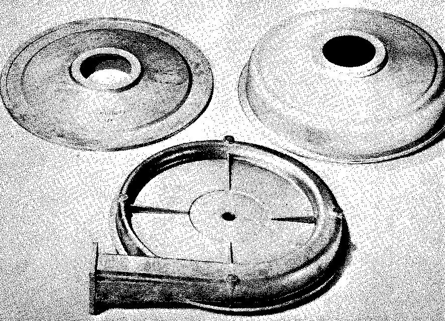
Drawings of parts for this process do not differ essentially from those made by precision investment molds or by die casting. In many cases, no machining at all is required. Detail drawings are used largely by the moldmaker and only in special cases by the machinist.
Finish symbols
For a discussion of finish symbols see Section Surface treatment of metals
Common terms used on castings
Fillets, rounds, and runouts
For a description of these see Sec. 5. Conventional representation
Ribs and webs
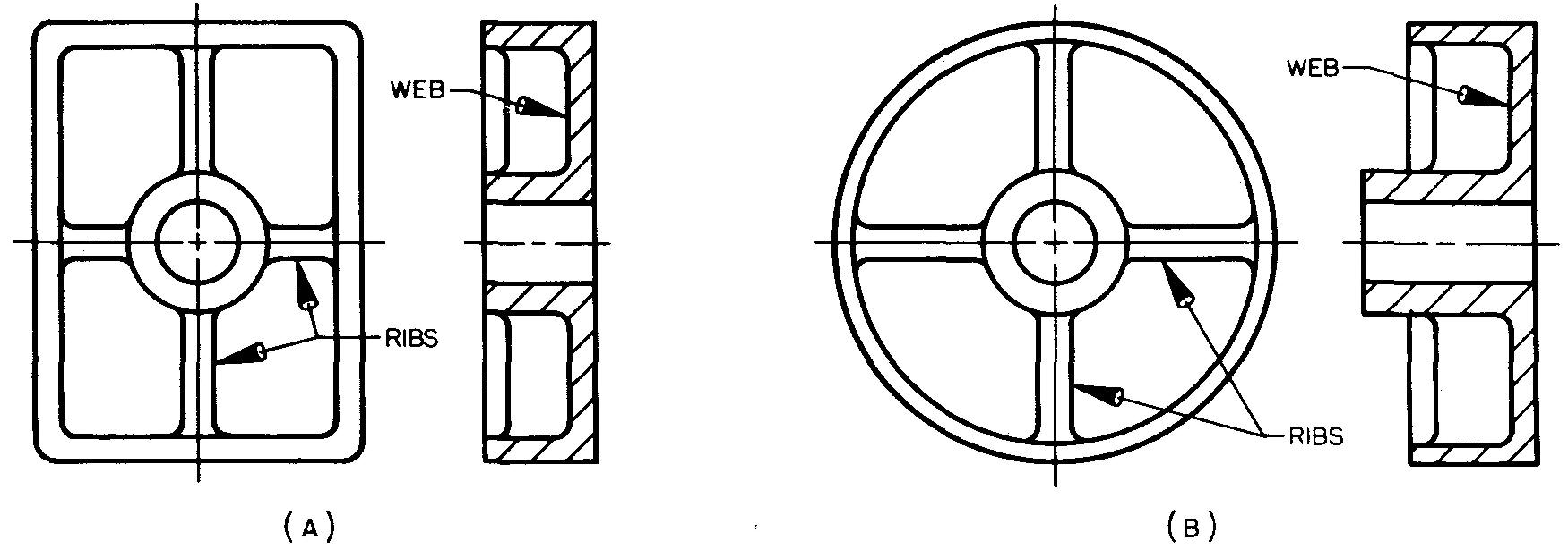
Ribs and webs, shown in Fig. 14-20, are msed to stiffen and strengthen different members of a part. While the terms rib and web are often used to describe the same feature, each may be slightly different. A rib is used to support members of a part. A web connects members of a part.
Fig. 14-20. Ribs and webs
Bosses and pads
A boss is a raised flat cylinder which projects above a surface. A pad is also a raised surface, but it may be square, rectangular, or some other shape. Both bosses and pads (Fig. 14-21) provide extra thickness in certain areas and save machining over larger surfaces.
Fig. 14-21. Bosses and pads
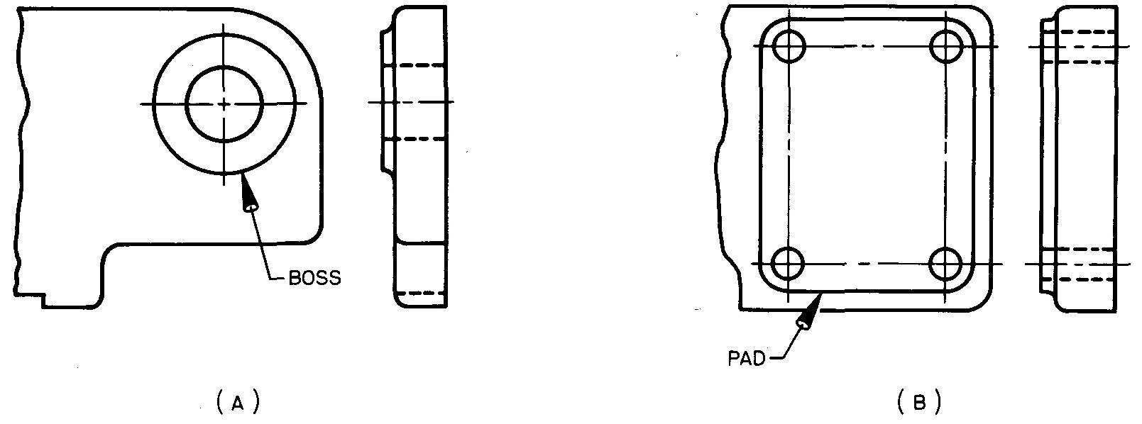
Bosses and pads also help to cut down unnecessary weight, since the surfaces are made extra thick only where necessary.
Lugs
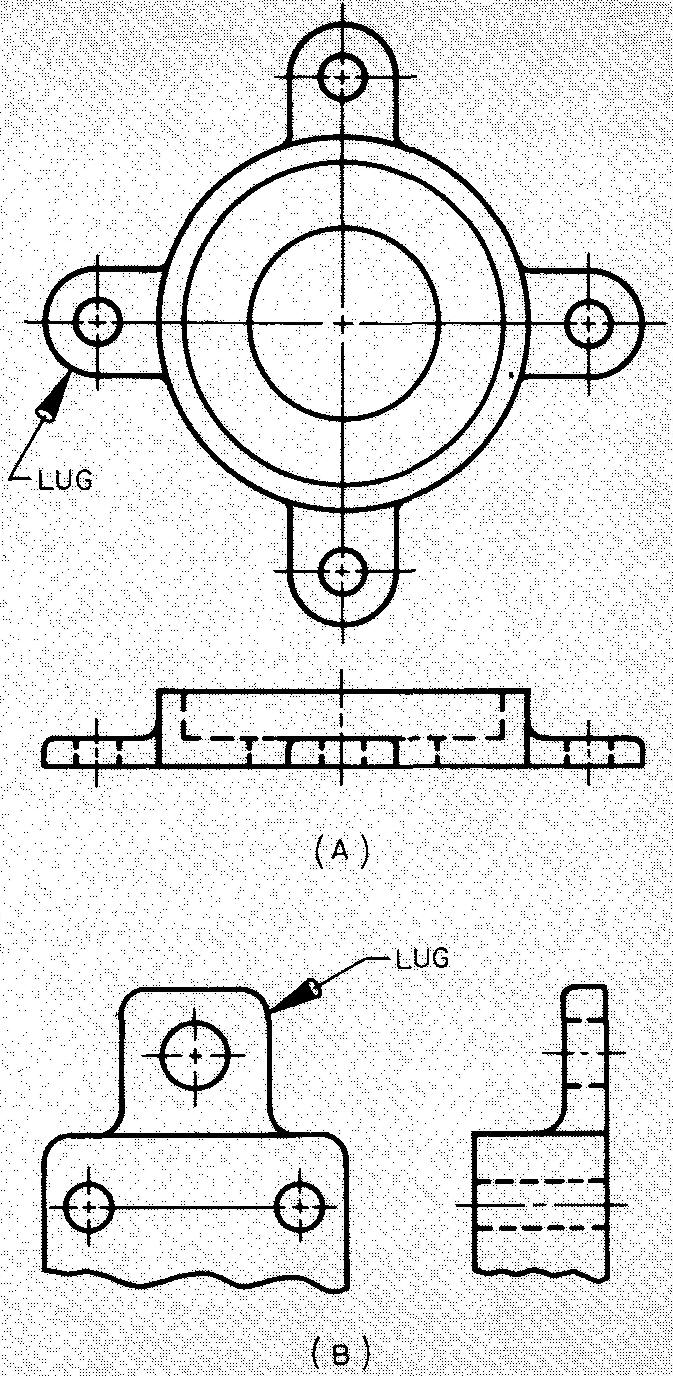
A small extension of a part, Fig. 14-22, is called a lug. It is usually rectangular in cross section. Lugs are often referred to in the shop as ears. Holes are generally drilled in lugs as a means of fastening or holding one part to another.
Fig. 14-22. Lugs
Sizes of fillets and rounds
The selection of the size of the fillets and rounds to be used on castings is usually left to the discretion of the machine draftsman. In some cases, the strength of a casting may be doubled by the addition of certain fillets.
The size of the fillet depends upon the kinds of metal used, the shape and thickness of the wall section nearest the fillet, and the overall size of the casting. Fillets and rounds with unnecessarily large radii should be avoided. In the selection of the size for the radius of a fillet or round, the following rules are recommended.
For sections of equal thickness
Use a radius equal to the thickness of the section, as shown in Fig. 14-23A.
Fig. 14-23. Fillet sizes
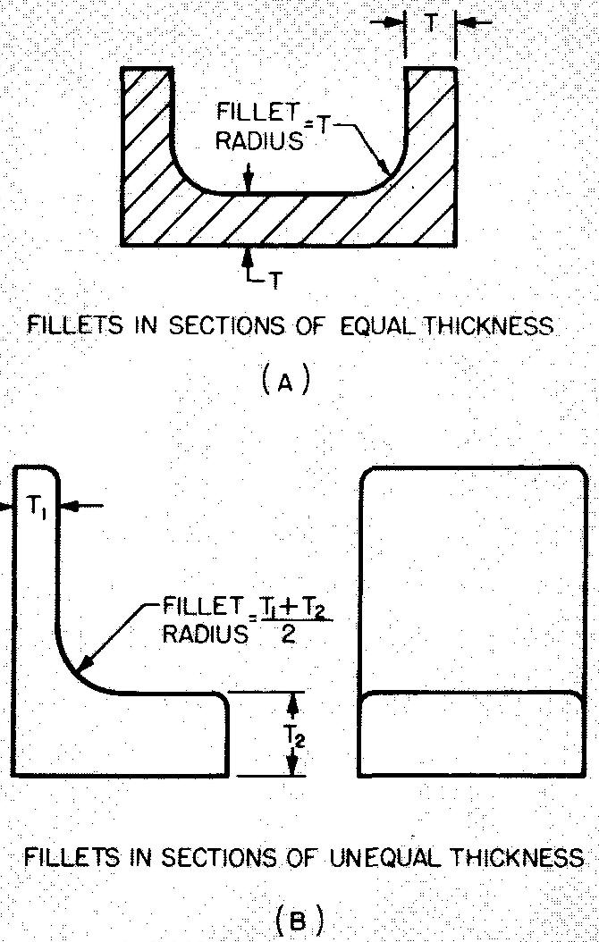
For sections of unequal thickness
Use a radius equal to the average thickness of the two sections, as shown in Fig. 14-23B.
Sizes of bosses and lugs
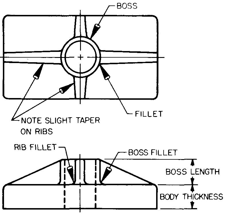
The length of a boss or the thickness of a lug should be approximately equal to the main body thickness of the casting. Bosses and lugs should be filleted to make the change in size as gradual as possible.
Ribs attached to bosses should be strengthened by fillets. The thickness of the ribs should be greatest near the boss, with a slight taper extending outward, as shown in Fig. 14-24.
Fig. 14-24. Intersection of a boss and a rib
Sizes of ribs and webs
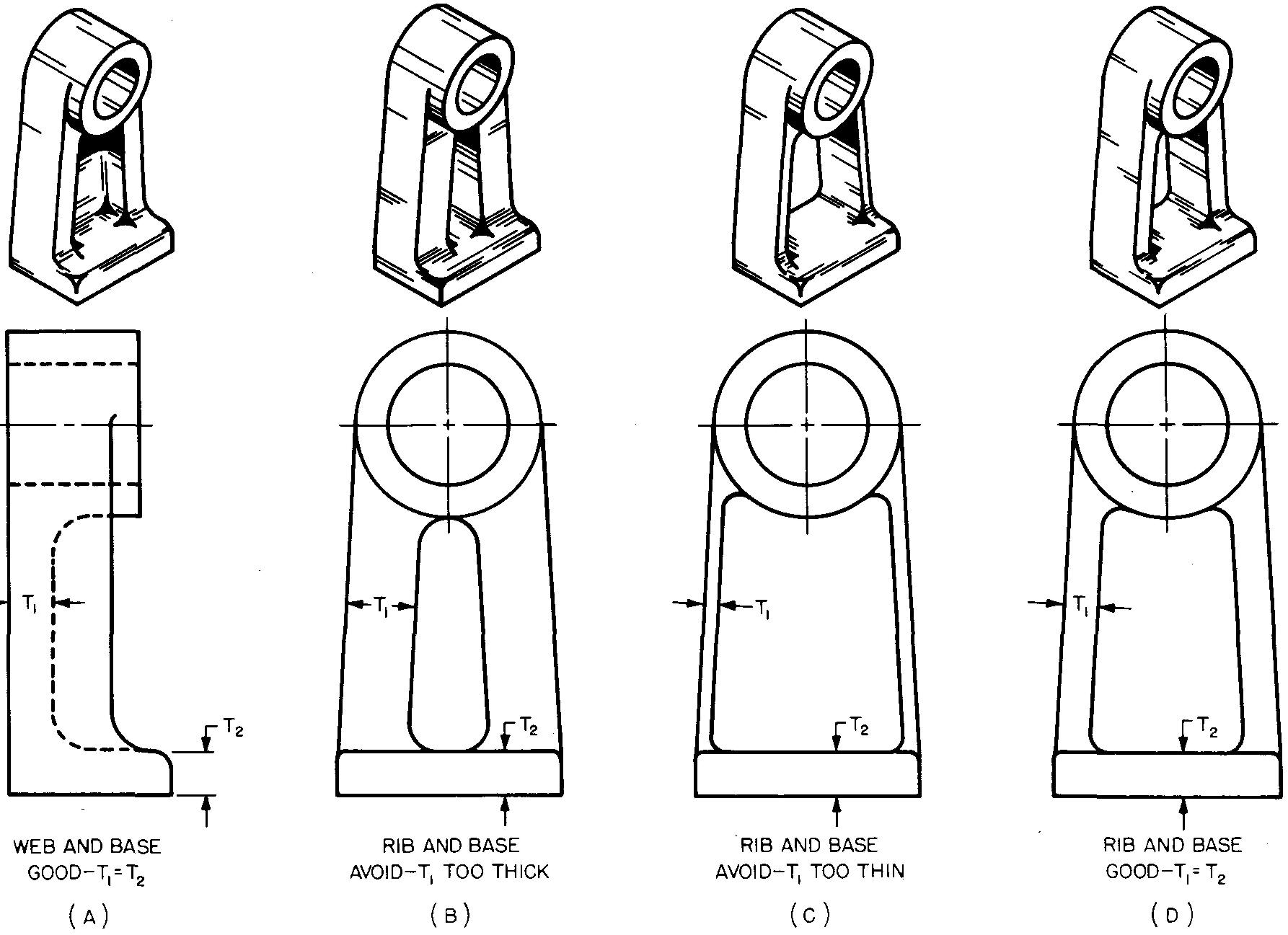
The thickness of these members is usually made less than or equal to the thickness of the part of the casting which they support or connect, as shown in Fig. 14-25.
Fig. 14-25. Sizes of ribs and webs
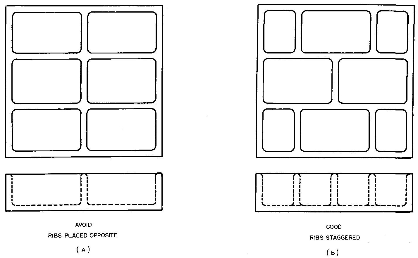
When ribs are used to reinforce large flat areas, they should be staggered, as shown in Fig. 14-26. Fillets and rounds are always used to support ribs and brackets on cast parts.
Fig. 14-26. Staggered ribs
Section thicknesses
In the design of cast parts, the best practice is to use the least amount of thickness which will provide the necessary strength.
It is recommended that brass and bronze parts be designed with a minimum thickness of 3/32 inch; iron and aluminum parts with a minimum thickness of 1/8 inch; and steel with a minimum thickness of 3/16 inch.
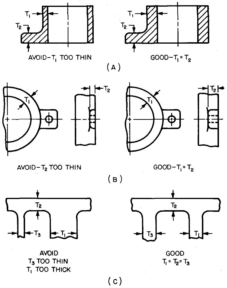
When two sections of a casting intersect, as shown in Fig. 14-27, the thickness of one section should be equal to or slightly more than the thickness of the other section.
Fig. 14-27. Intersecting sections of parts
Casting design
The design engineer follows a few general rules in choosing the process by which a part should be cast. Among the design factors which he must consider are: sectional thickness requirements, size and weight of the final parts, intricacy of shapes and cores, dimensional tolerances desired, and the required surface finish.
The required quantity of parts, desired physical properties, and the amount of subsequent machining and finishing are also factors affecting his decision.
The final choice of process is often dictated by the most economical method of producing the parts in the desired quantities.
See 14. Forming parts by casting Review questions
