Forming parts by casting Review questions
1. What are some of the factors which govern the selection of the best method for casting a machine part?
2. Briefly describe the process of sand casting.
3. What are some of the common metals used in the sand-casting process?
4. Why must the patternmaker provide shrinkage allowance on a pattern?
5. Describe a shrink rule and tell how it is used.
6. What special symbol on a drawing tells the patternmaker where to add stock for machining allowance!
7. Describe the use of a flask in sand casting. What are the two main parts?
8. Explain the use of a parting line on ; pattern. Is the position of the parting line shown on the drawing? Explain.
9. What is the purpose of draft! Is the amount of draft specified on a drawing
10. Who is responsible for determining the construction details of the pattern?
11. What is the purpose of a core!
12. Describe how a core is held in its proper position in a sand mold.
13. In a sand casting, the metal is poured into the impression left by the pattern through a hole in the sand. What is this hole called?
14. In a sand casting, gases escape through the porous sand and through holes made for this purpose. What are these holes called?
15. After pouring the metal, how is the sand core removed?
16. Briefly describe the process of die casting.
17. Explain why die casting is considered economical only in the production of a large quantity of parts.
18. What is done to the mold in die casting so that several parts may be molded at the same time?
19. What are the major advantages of the die-casting process?
20. Explain the reason why iron and steel parts cannot be made by the die-casting process.
21. List some of the metals which are more commonly used for die casting.
22. Are separate drawings prepared for the diemaker and the machinist for die-cast parts? Explain.
23. Which of the following words describes the amount of machining necessary for die-cast parts? (a) Great, (b) Moderate, (c) Little, if any.
24. Prepare a brief outline to describe the process of precision investment casting.
25. Approximately when was the precision investment casting process adapted for commercial and military use in the U.S.?
26. What are the major advantages of this process?
27. What are some of the limitations?
28. Briefly describe the process of permanent mold casting.
29. How does this process differ from sand casting? Give the advantages of permanent mold casting.
30. How would you compare the production rate of permanent mold castings to the production of sand and die castings?
31. What are some of the common metals used in the permanent mold process?
32. Why is the process generally limited to parts with reasonably simple shapes?
33. What is meant by a finished surface?
34. When a machine part is to be machined all over, should finish marks be applied to each surface? Explain.
35. Make a freehand sketch of one or more parts showing the following features:
a. fillet. b. round,
c. rib.
d. web.
e. boss. f. pad.
g. lug. h. runout.
Problems
Prepare detail drawings of the problems which are shown on the following pages. It will be necessary to study all of the information contained on the illustration and also the data which accompany each problem.
References have been provided for the important elements of each problem such as machining and manufacturing processes, drafting mathematics, heat treatment, hardness testing, tolerancing, information listed in the Appendix tables, and so on.
The references listed for each problem pertain only to material not found in section 2 through 7 and in section 14. All references should be carefully checked before starting the problem.
Space the required views carefully on the drawing sheet, allowing sufficient space around the views for dimensions and notes.
For each problem prepare a detail title consisting of the part number, part name, pieces per unit, material, and the finish specifications, heat treatment, and hardness test number as required.
Important — In most cases, only the critical dimensions of each part have been given. Sizes of some of the less important features of parts have been intentionally omitted leaving the selection of these sizes to the discretion of the student.
For drawing purposes, features of parts which appear to be located on center with corresponding edges may be assumed to be central.
It is important for the student to give those dimensions which locate all of the features of the part, thus eliminating any possibility of guesswork if the drawings were to be actually used in the shop.
Do not copy the given dimensions. In many cases, the given dimensions would not be suitable for use on a two or three-view detail drawing.
Problems in this section are all similar in that each one is formed by a casting process.
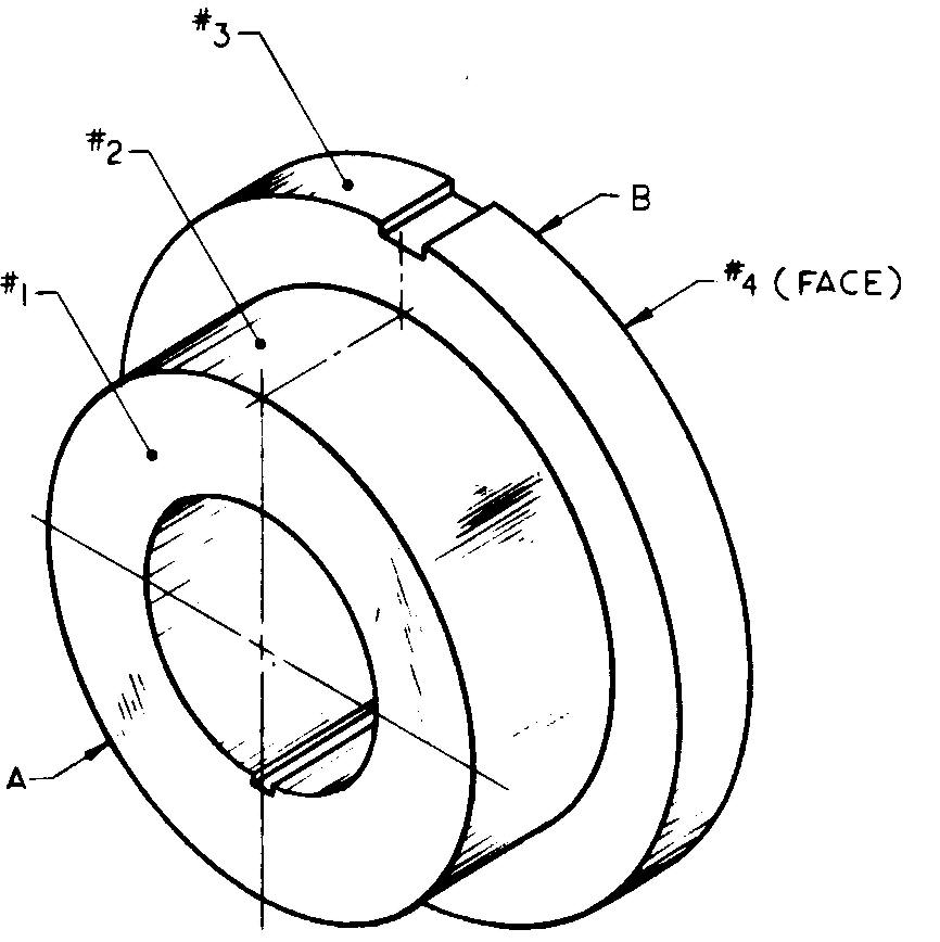
problem 14-1 spacer

Sheet Size 8-1 /2 x 11 Drawing Scale Full
Material Aluminum Alloy B356
Pieces per Unit 8 Casting Process Permanent Mold Finished Surfaces #1, #2, #3, and #4 Required Finish Symbol V
References Sees. 8 (Figs. 8-21 and 8-22), 11, 12 (Fig. 12-48), (Figs. 12-51 and 12-52), and (Fig. 12-65); Tables 6 and 48 Annodize finish.
Specify "All dias must be concentric and square with faces within +0.003 T.I.R." (Total Indicator Reading is the result obtained from an instrument known as a dial indicator gage. It is used to check the concentricity of the three diameters of the spacer.)
Slots on dia B — 3/16 wide x 1 /16 deep, 9 equally spaced
Hole — 1-5/8 dia, tolerance +.010 Keyway — To fit 1 /8 square key
Corner radii not to exceed .010 A — 3 dia x 1" lg, tolerance +.0025 B — 4 dia x 1 /2 lg, tolerance +.0025
Problem 14-2 faceplate
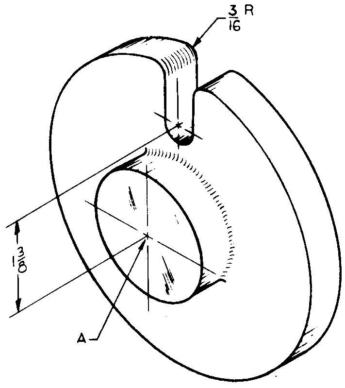
Sheet Size 8-1 /2 x 11 Drawing Scale Full
Material Gray Cast Iron Pieces per Unit 1
Casting Process Permanent Mold
References Sees. 12 (Fig. 12-21), (Fig. 12-42), 12.22 (Figs. 12-51 and 12-52), and (Flange; Fig. 12-70); Table 8
Specify "Remove all sharp corners."
Center hole A - 1 "-8 UN ?-2 threads, 1-1/4 dia counterbore x 1/4 deep from back Flange — 4" dia x 1 /2 thick Slot — 7/16 wide Hub - 2 dia x9/16 lg
problem 14-3 threaded bushing
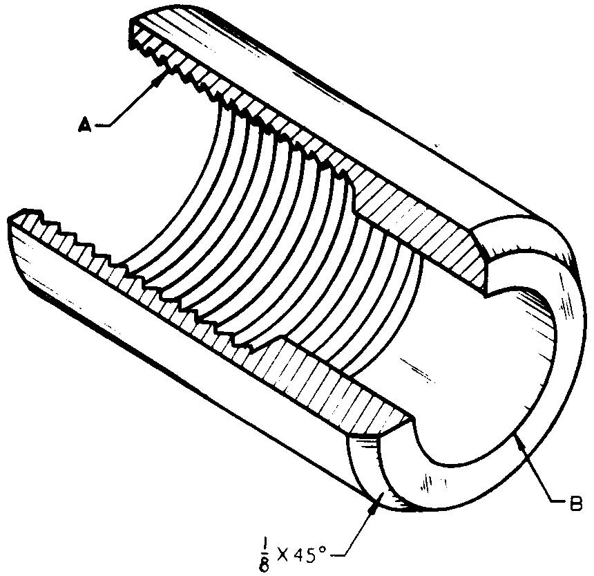
Sheet Size 8-1 /2 x 11 Drawing Scale Optional
Material Aluminum #346 Pieces per Unit 2
Final Part Size 1 -1 /2 dia x 2 Ig Casting Process Investment Casting
References Sees. 11, 12 (Fig. 12-40), (Fig. 12-42), and (Fig. 12-56); Table 8
Half-sectional view required. A - 1-1/4-7 UN?-3 threads x 1-1/4 deep, use detailed thread symbol B — .750 dia, tolerance +.001, -.002
problem 14-4 latch plate
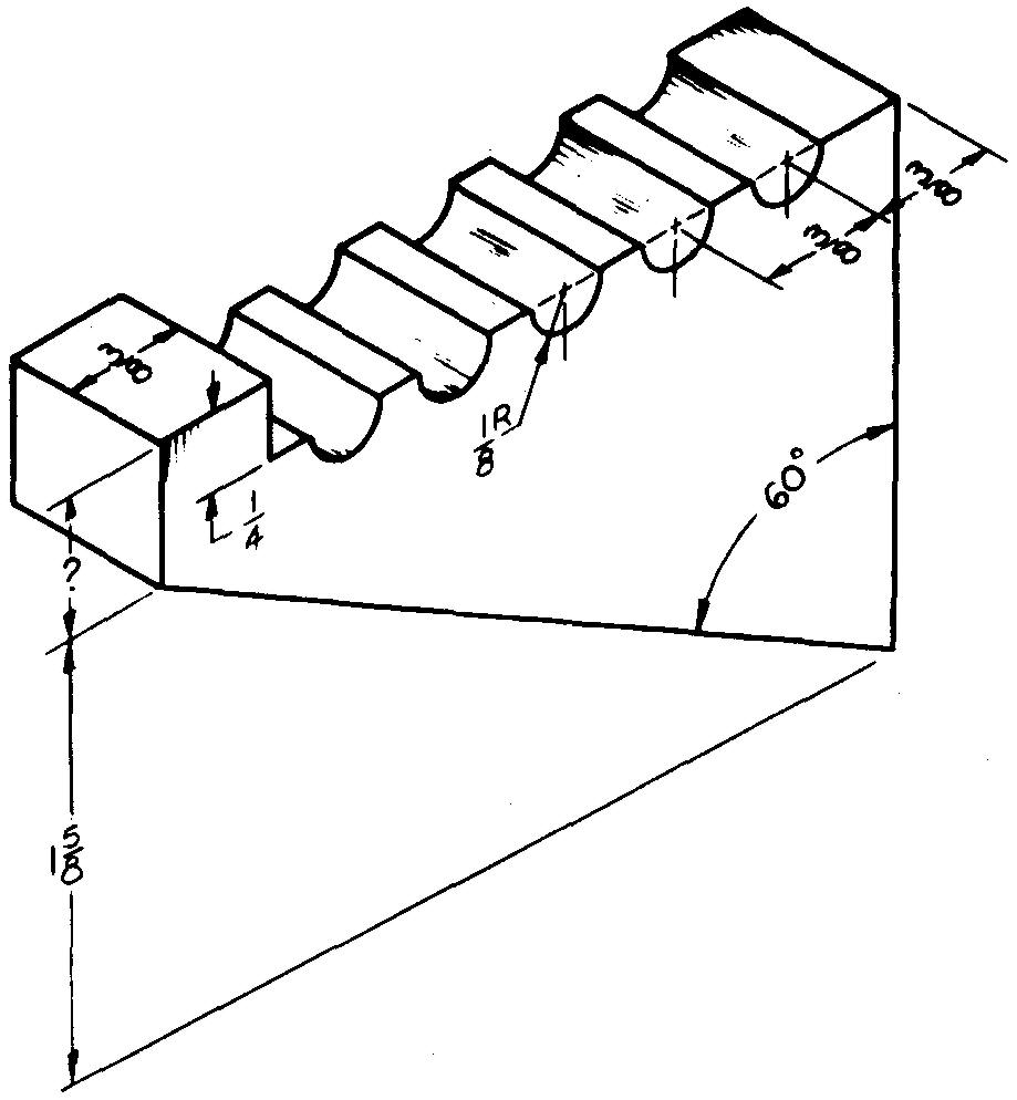
Sheet Size 8-1 /2 x 11 Drawing Scale Optional
Material Aluminum #13 Pieces per Unit 2
Final Part Size 1 /2 thick x 1 -5/8 wide x 2-1 /2 lg
Casting Process Investment Casting
References Sees. 10; Table 4 Calculate and specify the total weight.
problem 14-5 end cap

Sheet Size 8-1 /2 x 11 Drawing Scale Optional
Material Copper Pieces per Unit 1 Final Part Size 3/4 lg
Casting Process Permanent Mold
References Sees. 10,11,12 (Fig. 12-35), and (Fig. 12-42); Table 4 Half-sectional view required.
Calculate and specify the total weight.
A — 1-7/8 dia
B - 2 dia x 7/32 lg
C — 1- /8 dia basic size, tolerance +.002
D — 1-9/16 dia basic size, tolerance ±.002, 1 /4 deep
E — 1/4-20 UN?-2 threads, use schematic thread symbol
All radii 1/16
problem 14-6 end bracket

Sheet Size 8-1/2 x 11 Drawing Scale Optional
Material Gray Cast Iron Pieces per Unit 2
Casting Process Sand Casting
Finished Surfaces #1, #2, and hole J
Required Finish Symbol f
References Sees. 11, 12 (Fig. 12-6), and (Fig. 12-25); Tables 13 and 31
A - 4-5/8
B - 7-1/2
C - 3/4
D - 8
E - 5/8
F - 5-1/2
G - Clearance holes and spotface for two 7/16 dia hexagonal-head cap screws, located 5-1 /2 center to center and 1 -1 /8 from front edge
H — Clearance holes and spotface to fit four 3/8 dia tie rods with hex nuts, located on 6-1 /2 BC
J — 4-1 /2 dia bore, tolerance +.002, -.000
problem 14-7 trip lever

Sheet Size 8-1/2 x 11 Drawing Scale Twice
Material Zinc Pieces per Unit 3
Casting Process Investment Casting
References Sees. 11, 12 (Fig. 12-41), and (Fig. 12-42); Table 8
A-7/8 dia C-1/16R
B - 1 /2-20 UN ?-2 threads, 5/8 deep
problem 14-8 adjusting cap
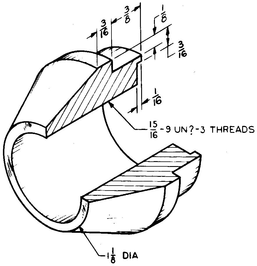
Sheet Size 8-1/2 x 11 Drawing Scale Twice
Material Dow Metal C
Pieces per Unit 6
Final Part Size 1 -13/16 dia x 1 -3/4 lg
Casting Process Investment Casting
References Sees. 10, 12 (Fig. 12-36), and (Fig. 12-42); Table 8 Half-sectional view required. Use simplified thread symbol.
Calculate and specify the taper angle.
problem 14-9 bushing
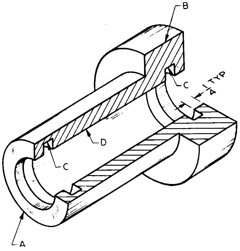
Sheet Size 8-1/2x11
Drawing Scale Full
Pieces per Unit 2
Material Copper Alloy #68
Final Part Size 4 lg
Casting Process Permanent Mold
Finish Surfaces Grooves only Required
Finish Symbol V
References Sees. 8 (Figs. 8-21 and 8-22), 11, and 12 (Fig. 12-60) Half-sectional view required.
A — 1.753 dia, tolerance +.0000, -.0005
B — 2-3/4 dia x1"lg
C — 1.500 dia, tolerance +.001, 1 /4 wide
D — 1.250 dia, tolerance +.002
problem 14-10 sliding block

Sheet Size 8-1 /2 x 11 Drawing
Scale Twice
Material Silicon Brass
Pieces per Unit 2
Casting Process Investment Casting
References Sees. 12 (Fig. 12-4) and (Fig. 12-48)
A — 3/16 drill through, 3/8 ream, 1-1 /4 deep
B - 3/8 drill, 2 holes
problem 14-11 locating plate
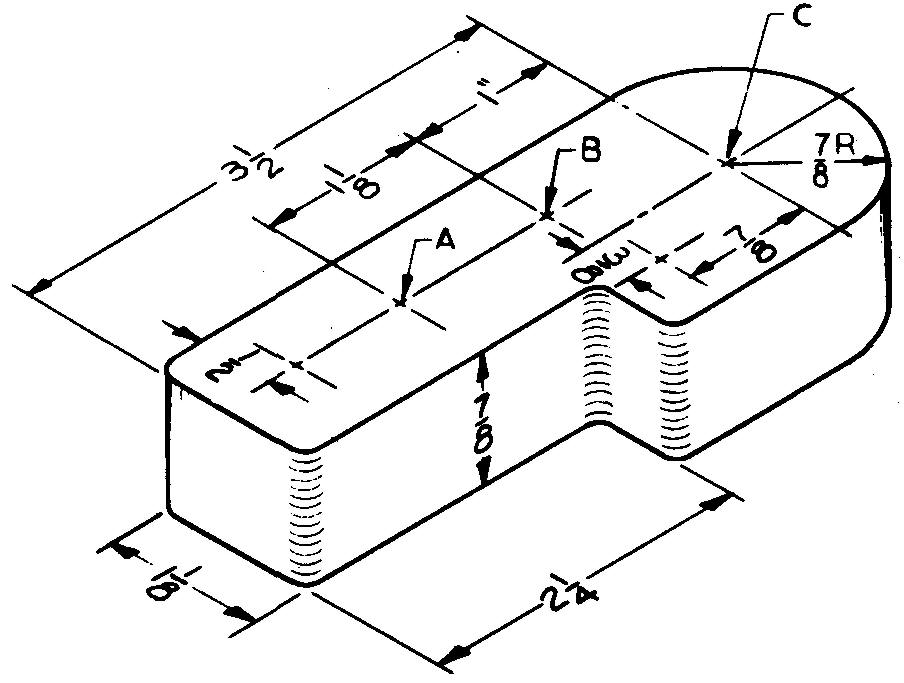
Sheet Size 8-1 /2 x 11
Drawing Scale Full
Material Aluminum #43
Pieces per Unit 1
Casting Process Investment Casting
References Sees. 10, 12 (Fig. 12-21), and (Fig. 12-48); Tables 4 and 14
Specify "All fillets and rounds 1 /8 radius."
Calculate and specify the total weight.
Disregard fillets and rounds.
A — 1 /4 ream through, 2 required
B — Drill and counterbore for 3/8 socket-head
cap screws, 2 required, locate 1-15/16 center to center
C — 5/8 ream through, boss on bottom surface centered with hole C, boss size 1 /8 x 1 -1 /4 dia
problem 14-12 coupling
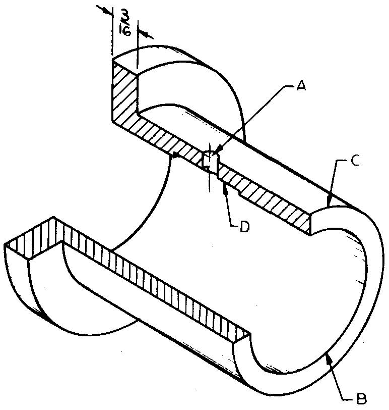
Sheet Size 8-1 /2 x 11
Drawing Scale Twice
Material Aluminum Bronze
Pieces per Unit 1
Final Part Size 1-5/8 dia x 1-1 /2 lg
Casting Process Investment
Casting References Sec. 1
Half-sectional view required.
Specify "Maximum fillet and round radius + 0.015."
A — 1/8 dia hole, locate on center with ends
B — .875 dia, tolerance +.002, +.003
C — 1-1/8 dia
D — 1/16 square slot x 1/2 lg, located central with hole A
problem 14-13 sanding disc
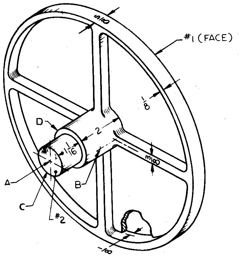
Sheet Size 8-1/2x11
Drawing Scale Half
Material Zamak #5
Pieces per Unit 1
Final Part Size 9-7/8 OD
Casting Process Die Casting
Finished Surfaces #1, #2, and dia C
Required Finish Symbol V
References Sees. 11, 12 (Fig. 12-48), (Fig. 12-69), and (Shoulder; Fig. 12-72) (Face; Fig. 12-73); Table 38
Half-sectional view required.
Specify "Rim must be concentric with hole within +0.0025 T.I.R."
A — 5/8 ream, 2-3/8 deep
B — Hole for #4 x 2 lg taper pin, locate 3/8 from square shoulder
C — 1-11/32 dia, tolerance +.001, -.002 D - 2 dia
problem 14-14 air brake stand
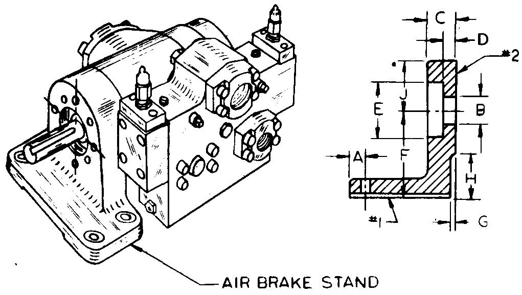
Sheet Size 8-1/2x11
Drawing Scale Optional
Material Gray Cast Iron
Pieces per Unit 1
Casting Process Sand
Casting Finished Surfaces #1 and #2
Required Finish Symbol V
References Sees. 8 (Fig. 8-21 and 8-22), 11, and 12 (Fig. 12-25); Tables 13 and 14 Full-sectional view required.
A — 1/2
B — 1" dia hole (basic size), tolerance +.0025 +.0003
C — 1"
D — 27/64
E — 2-3/32 dia (basic size), tolerance +.005
F — 3
G - 1 /4
H — 1-1/4
J — 2R
Base holes — Drill and spotface to fit 5/16 dia
hexagonal-head cap screws, 4 required, locate 1-1/2 and 5 center to center.
Equally spaced holes (shown in pictorial view only) — To fit 1 /4 socket-head cap screws, 8 required, located on 3-1 /16 BC
Base Size — 11/16 (including pad thickness) x 2-1/2 x 6
Base pads -1/8 x 1-1/4 x 2-1 /2
problem 14-15 yoke base
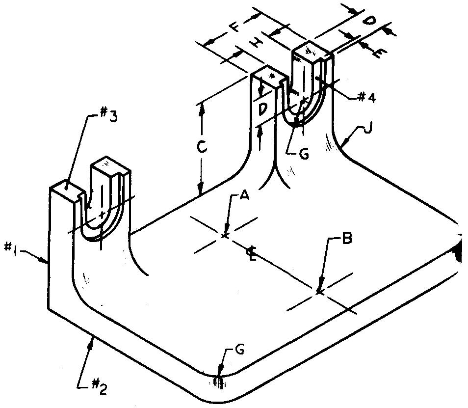
Sheet Size 11x17
Drawing Scale Optional
Material Aluminum #43
Pieces per Unit 2
Final Part Size Base — 3/8 thick x 2-11 /16 wide x 4lg
Casting Process Sand Casting
Finished Surfaces #1, #2, #3, #4, and slots H &G
Required Finish Symbol f
References Sees. 8 (Figs. 8-21 and 8-22), 12 (Fig. 12-4), (Fig. 12-48) and (Figs. 12-51 and 12-52)
Two drawings required:
1) A pattern drawing (1/8-inch machining allowance).
2) A machining drawing. Use a separate sheet for each drawing.
A — 5/8 ream through, locate 1-1/2 from B
B — 7/16 drill through, locate 7/16 from front edge
C — 1-1/4
D — 3/8
E — 1/16
F — 7/8
G — 3/8R
H — 13/32
J — 1/2R (typical)
problem 14-16 positioning lug
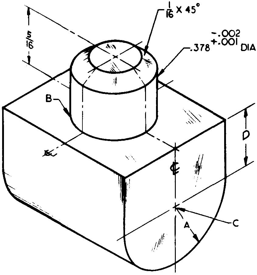
Sheet Size 8-1/2 x 11
Drawing Scale Optional
Material Brass Pieces per Unit 4
Final Part Size 3/4 lg
Casting Process Investment Casting
References Sees. 10,11,12 (Fig. 12-42), and (Fig. 12-56); Tables 4 and 8
Specify "0.378 dia must be centered with sides and ends within ±0.005 T.I.R."
Calculate and specify the total weight.
A — 5/16 R D-21/64
B — Radius not to exceed ±.010
C — 5 /16-18 U N ?-2 threads, LH
problem 14-17 adjusting knob

Sheet Size 8-1/2 x 11
Drawing Scale Optional
Material Zamak #3
Pieces per Unit 1
Final Part Size 1-1/2 dia x 1 -11/16 lg
Casting Process Die Casting
References Sees. 8 (Fig. 8-2 and 8-9), 11, 12 (Fig. 12-48), and (Fig. 12-56)
Full-sectional view required.
A — 1/8 ream through
B — .3125 dia hole, tolerance +.005, +.004
C — 1 -1/8 dia x 1/2 deep
D —1/2dia
E — 3/32 R
Surface #1 — Cast medium knurl 1/32 x 45° chamfer at both ends
problem 14-18 thrust knob
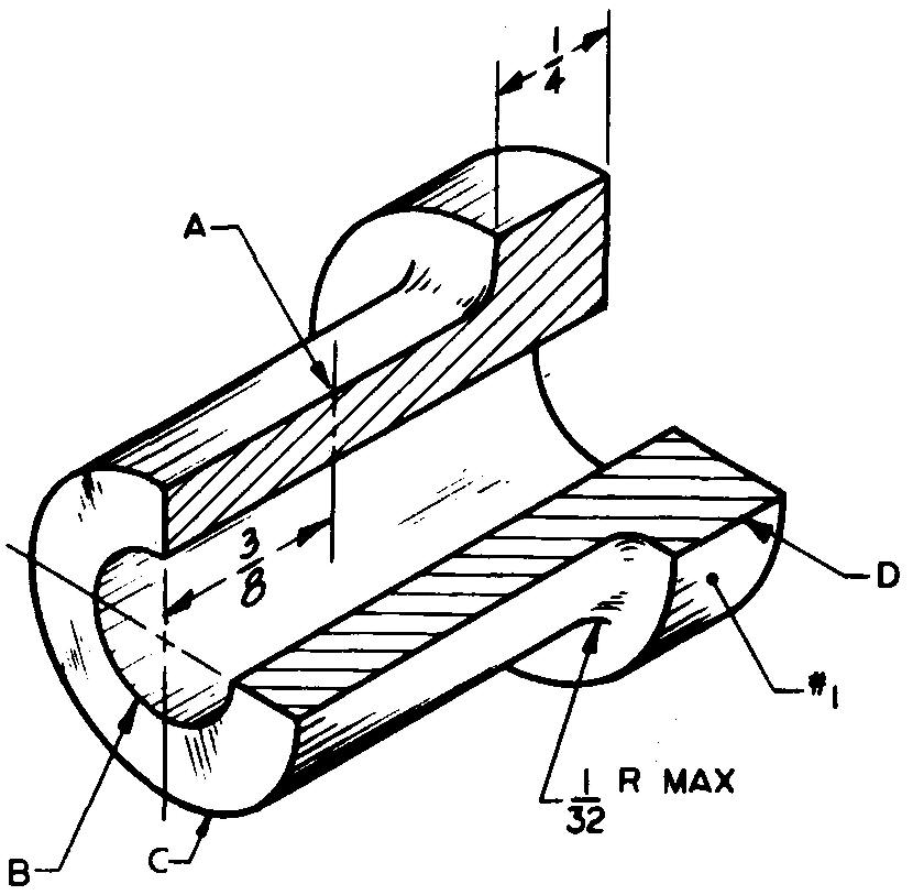
Sheet Size 8-1/2 x 11
Drawing Scale Twice
Material Zamak #3
Pieces per Unit 1
Casting
Process Die Casting
References Sees. 8 (Figs. 8-4 and 8-9), 11, 12 (Fig. 12-36), (Fig. 12-42), and (Fig. 12-56); Table 8
Half-sectional view required.
A — #6-32 UN?-2 threads, one side only, use simplified thread symbol
B — 3/8 dia hole (basic size), tolerance ±.005
C —5/8dia x 3/4 lg
D —7/8 dia
Surface #1 — Cast fine knurl
Chamfer — 1/32 x 45° both ends of dia D
problem 14-19 crank plate
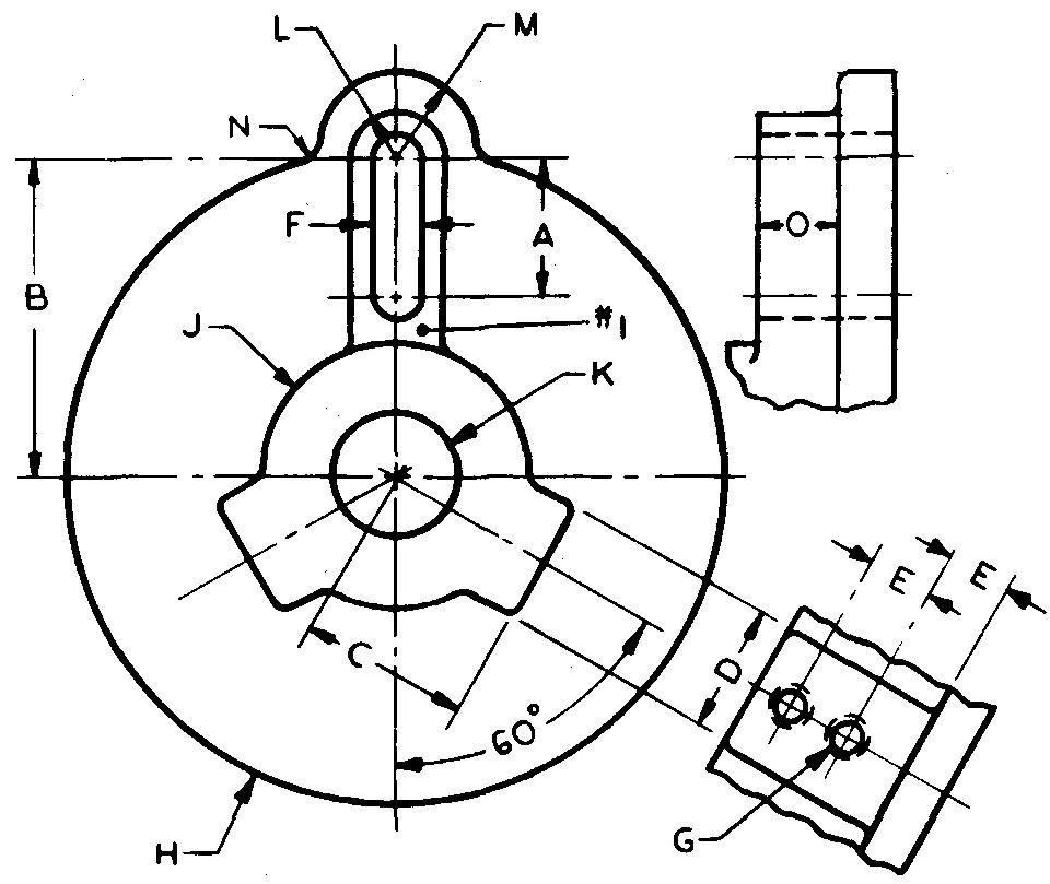
Sheet Size 11x17
Drawing Scale Full
Material Brass
Pieces per Unit 4
Casting Process Die Casting Finished
Surfaces #1 and back face
Required Finish Symbol f
References Sees. 8 (Figs. 8-21 and 8-22), 11, 12 (Fig. 12-36), (Fig. 12-42), (Figs. 12-51 and 12-52), and (Shoulder; Fig. 12-72); Table 8
Use a conventional representation for the sectional view.
A — 1-3/4
B — 4-1/4
C — 2-1/2
D — 2
E — 13/16
F — Clearance slot for 3/4 bolt
G — 1/2-13 UN ?-2 threads to hole K, 2 required in each lug, use simplified thread symbol
H — 8-1/2 dia x 5/8 thick
J — 1-7/8 R x 2-1/16 lg
K — 1-1/2 dia hole, tolerance +.002
L — 3/4R
M — 1-1/4R
N — 1/4R 0 - 1"
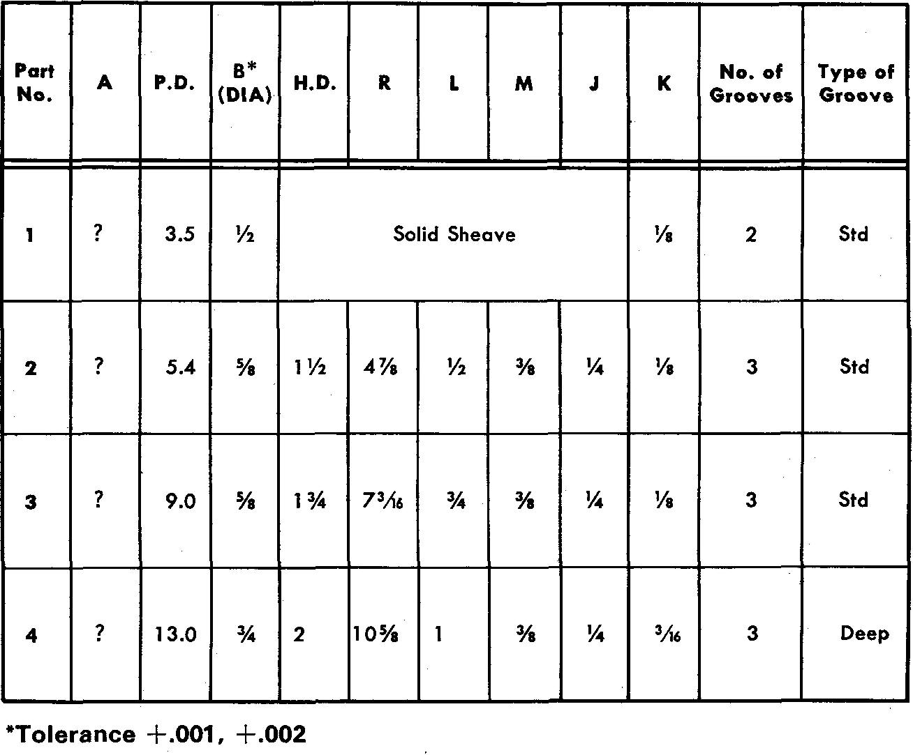
problem 14-20 sheave
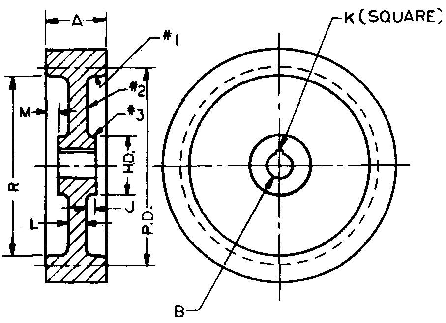
Sheet Size Optional
Drawing Scale Optional
Material Bronze
Pieces per Unit 4
Casting Process Sand Casting
Finished Surfaces FAO except #1, #2, and #3
Required Finish Symbol f
References Sees. 8 (Figs. 8-21 and 8-22), 11, and 12 (Fig. 12-65); Table 56
Draw Parts 1 through 4 as directed.
Show grooves.
Full-sectional view required.
Specify "Remove all sharp corners."
problem 14-21 hand wheel
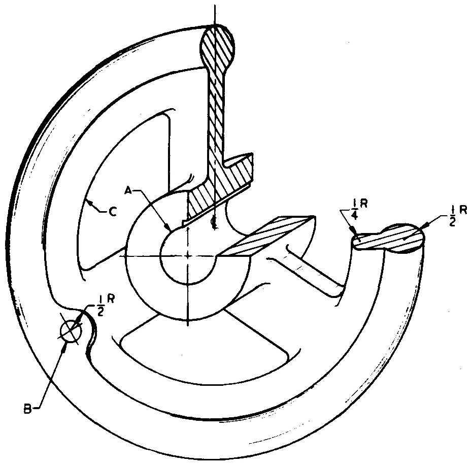
Sheet Size 11x17
Drawing Scale Full
Material Gray Cast Iron
Pieces per Unit 1
Final Part Size 9-1/40D
Casting Process Sand Casting Finished
Surfaces Hub ends only Required Finish Symbol /
References Sees. 8 (Figs. 8-21 and 8-22), 12 (Fig. 12-48), (Fig. 12-65), and (Hub; Fig. 12-71); Tables 6 and 48
Barrel tumble finish.
Full-and revolved-sectional views required
A — Ream for 1" dia shaft, install 1/4 square key
B — 3/8 ream through, locate 3-1/4 from center hole
C — 6 dia
Spokes — Rectangular cross section, 1/2 x 1"
Hub — 2 dia x 1-3/4 lg, ends centered with rim
problem 14-22 connecting flange
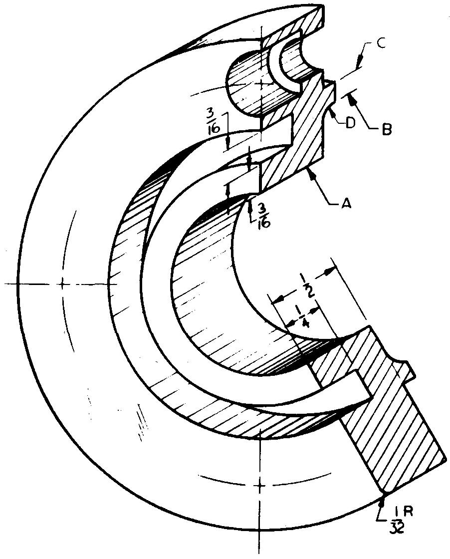
Sheet Size 8-1/2 x 11
Drawing Scale Full
Material Gray Cast Iron
Pieces per Unit 1
Final Part Size 3-1/4 dia x 19/32 lg
Casting Process Permanent Mold
References Sees. 11 and 12 (Fig. 12-21); Table 14
Half-sectional view required.
A — 1-5/32 dia hole B — 1-7/8 dia
C — 2-1 /8 dia, tolerance +.001, +.002
D — 1/8R
Holes — Drill and counterbore for 1/4 socket-head cap screws, 4 required, equally spaced on 2-5/8 BC
problem 14-23 pressure plate
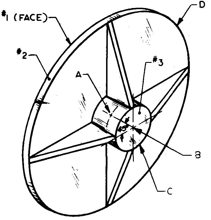
Sheet Size 8-1/2x11
Drawing Scale Half
Material Aluminum #43
Pieces per Unit 1
Casting Process Sand
Casting Finished Surfaces #1, #2, and #3
Required Finish Symbol f
References Sees. 8 (Figs. 8-21 and 8-22), 11, 12 (Fig. 12-6), (Fig. 12-42), and (Flange; Fig. 12-70); Table 8
Specify "Surfaces #1 and #3 must be parallel within +0.002 T.I.R.
Fillets and rounds 1/8 R."
A — 1 /4-20 UN?-2 threads, locate as shown, 1 /2 in from surface #3
B — 1.1875 dia bore, tolerance ±.002, 1-1/16 deep
C — 2-1/4 dia x 1-3/16 Ig to flange
D — 8-11/16 dia x 5/16 thick
Ribs — 1 /4 thick, 4 required, equally spaced
problem 14-24 coupling
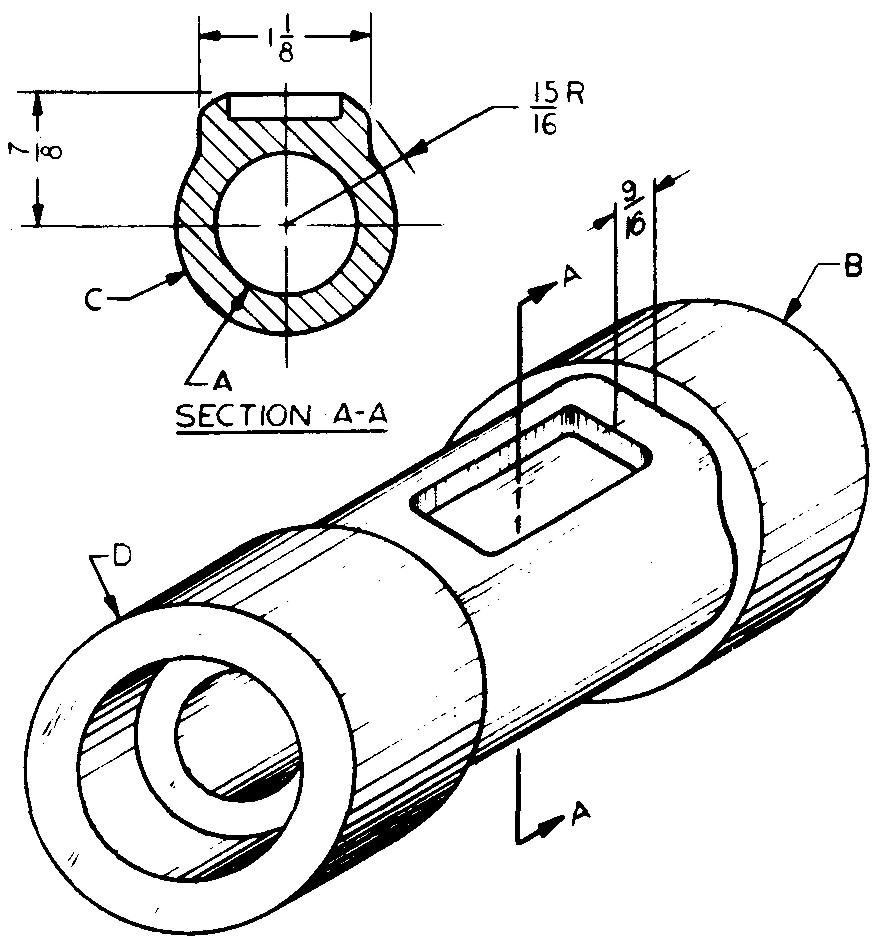
Sheet Size 8-1 /2 x 11
Drawing Scale Full
Material Dow Metal R
Pieces per Unit 1
Final Part Size 5-11 /16 lg
Casting Process Die Casting
References Sees. 11 and 12 (Figs. 12-51 and 12.52)
A removed-sectional view is required.
A — .875 dia hole, tolerance -.003, -.004
B — 2-5/32 dia x 13/16 lg
C — 11/16 R x 3-1/4 lg
D — 2-1/32 dia x 1-1/16 lg
Slot — 3/16 deep x 11/16 wide x 2-5/16 lg
End holes — 1-3/8 dia x 7/16 deep, both ends
problem 14-25 pulley housing

Sheet Size 8-1 /2 x 11
Drawing Scale Full
Material Aluminum #43
Pieces per Unit 1
Casting Process Sand Casting
Finished Surfaces #1, #2, and base
Required Finish Symbol f
References Sees. 8 (Figs. 8-21 and 8-22), 12 (Fig. 12-6), 12 (Fig. 12-25), and (Fig. 12-48); Table 13
A — 11 /16 ream through, 1-3/8 bore, 7/8 deep 2 required in line, one from each side, locate 5-3/4 up from base on center with 7-1 /2 dimension
B — Clearance drill and spotface for 3/8 hexagonal bolts, 4 required, locate 4-1 /4 and center to center
Base size — 1" thick x 5-3/4 wide x 8-1 /2 lg
Inner walls extend down to form the base opening
problem 14-26 special connector
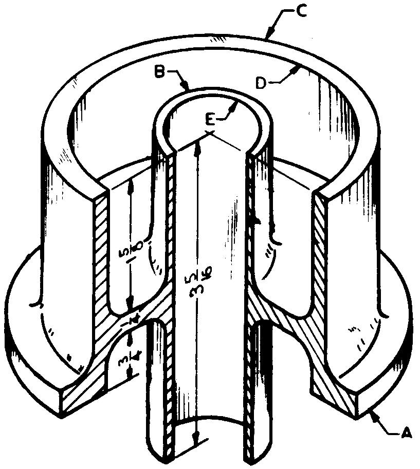
Sheet Size 11x17
Drawing Scale Optional
Material Aluminum B 195 Pieces per Unit 2
Casting Process Permanent Mold
Finished Surfaces Ends of dias A, B, and C
Required Finish Symbol f
References Sees. 8 (Fig. 8-2 and 8-22) and 11
A half-sectional view is required.
Specify "Diameters A and E must be concen trie with ±0.002 T.I.R."
A — 4-1/2 dia x 1/4 thick
B — 1-11/16 dia
C — 3-1/2 dia
D — 3-1/16 dia
E — 1-1 /16 dia hole, tolerance -.0020, -.0025
problem 14-27 special cone pulley
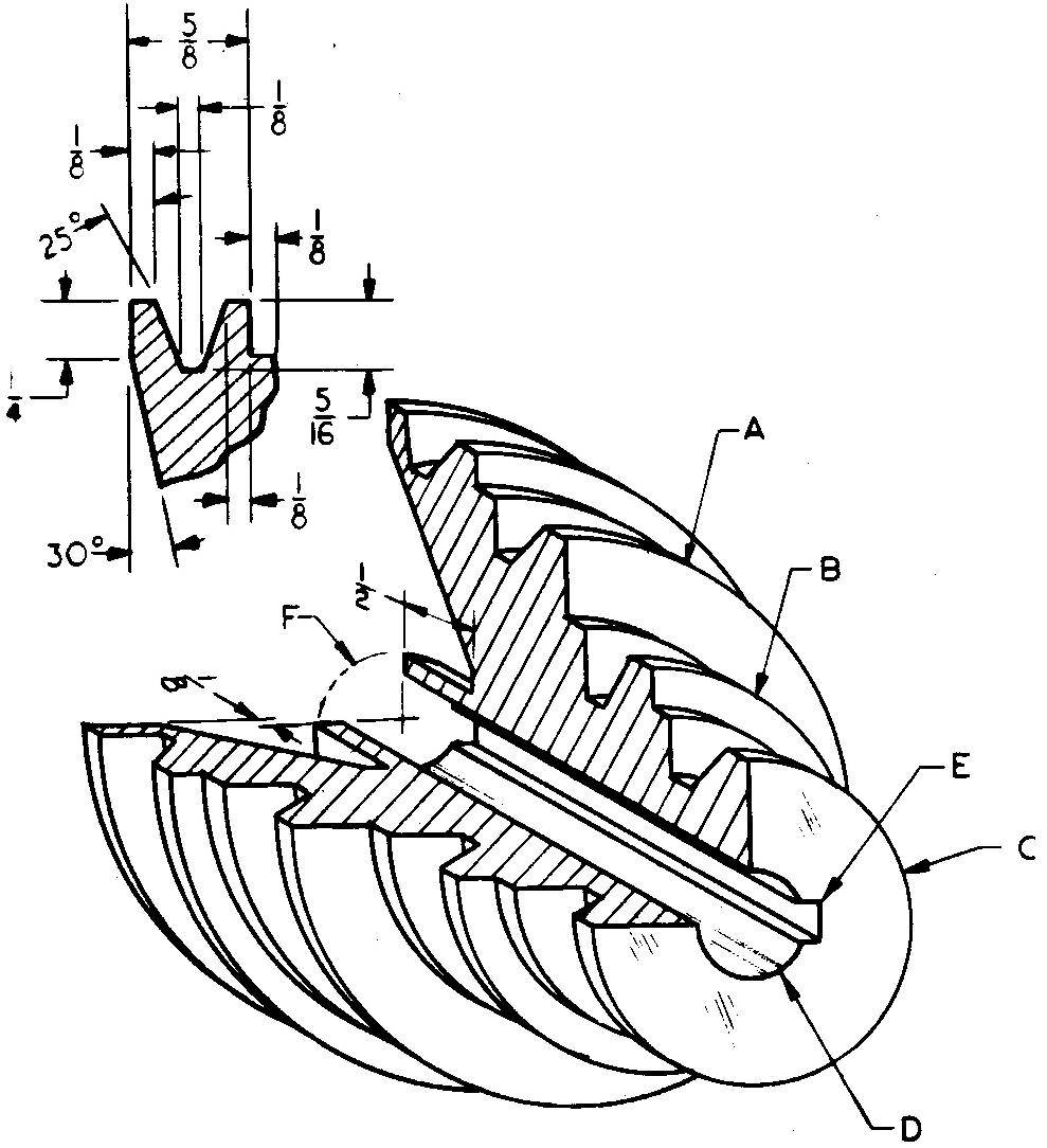
Sheet Size 8-1/2 x 11
Drawing Scale Optional
Material Aluminum #43
Pieces per Unit 3
Final Part Size 4 dia x 2-1/2 lg
Casting Process Sand Casting
Finished Surfaces FAO
References Sees. 10, 11, and 12 (Fig. 12-65); Table 48
Full-sectional view required.
Calculate and show on drawing the width dimension at top of V groove.
A — 3-1/2 dia
B — 2-1/2 dia
C — 2 dia
D — 5/8 dia hole, tolerance ±.005
E — 1/8 square key
F — 1" dia problem 14-28 handle
problem 14-28 handle
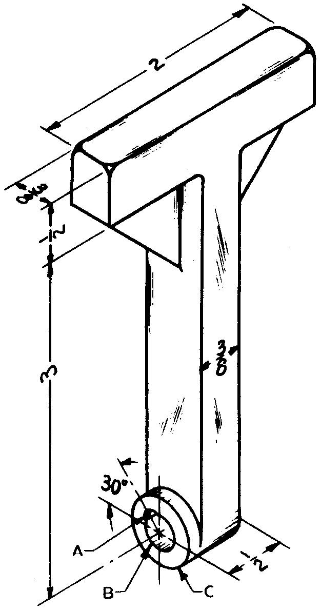
Sheet Size 8-1/2 x 11
Drawing Scale Full
Material Aluminum #43 Casting
Pieces per Unit 1
Process Die Casting
References Sec. 12 (Fig. 12-48)
A — 1/8 ream at assembly with shaft
B — 3/8 dia hole (as cast)
C — 3/4 dia, one side only
Ribs — 1/8 thick x 13/16 wide x 13/16 lg
problem 14-29 sander table
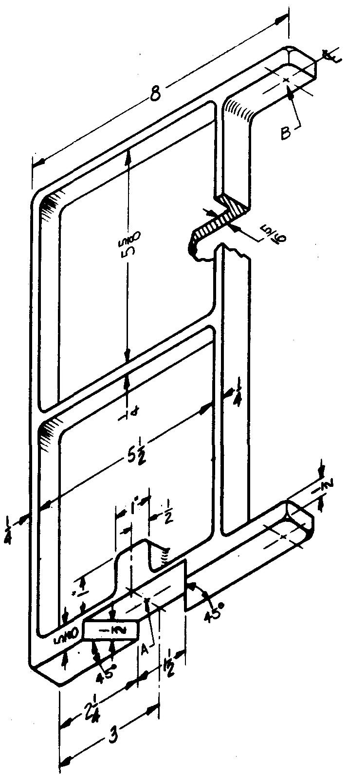
Sheet Size 11x17
Drawing Scale Optional
Material Aluminum #13
Pieces per Unit 1
Final Part Size 7/8 thick x 12-1/2 lg
Casting Process Die Casting
References Sec. 12 (Fig. 12-48)
Specify "Holes must be in line." Specify "Rounds 1/16 R maximum."
A — 1/2 ream, 3/4 deep
B — 3/8 ream, 2 required, locate 1/2 in from ends
problem 14-30 housing
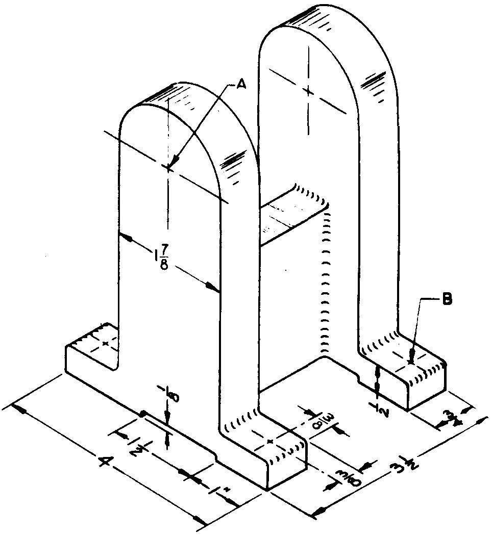
Sheet Size 11x17
Drawing Scale Full
Material Aluminum #43
Pieces per Unit 1
Casting Process Sand Casting
Finished Surfaces Base pads only
Required Finish Symbol f
Heat Treatment Stress relieve
References Sees. 9, 10, 12 (Fig. 12-21), and (Fig. 12-25); Tables 4 and 14
Two drawings required:
1) A pattern drawing (1/8-inch machining allowance).
2) A machining drawing. Use a separate sheet for each drawing.
Calculate and specify the total weight. Disregard fillets and rounds.
A — Clearance drill and counterbore for 5/8 socket-head cap screws, 2 required, locatec 4-1/2 up from base
B — Clearance drill and spotface for 3/8 socket-head cap screws, 4 required
Center rib — 5/8 x 2-1/2, located central with uprights.
problem 14-31 pillow block
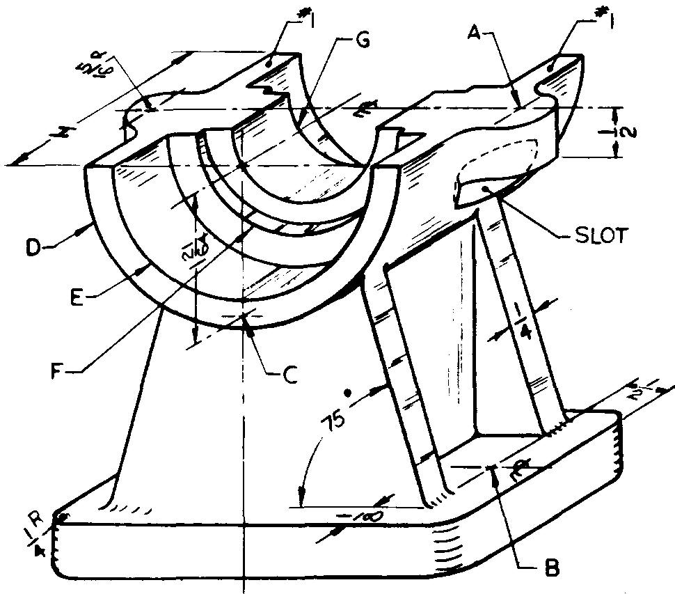
Sheet Size 11x17
Drawing Scale Twice
Material 1040 Steel
Pieces per Unit 2
Final Part Size 4 high
Casting Process Sand Casting
Finished Surfaces #1 and base
Required Finish Symbol f
Heat Treatment Normalize
References Sees. 9 (Normalizing), 11, 12 (Fig. 12.42), and 13 (Milling; Fig. 13-8); Tables 6 and 8 Parkerize finish.
A — Clearance drill for 1/4 bolts, 2 required, locate 3-3/8 center to center.
B — Clearance drill for 5/16 bolts, 2 required, 3 center to center
C — #5-40 UN ?-2 threads, 1/2 deep, 2 required (one hole on each side)
D — 3 dia
E — 2-5/16 dia, tolerance -.001, -.002, 5/8 deep
F — 2 dia, tolerance +.001, -.000, 1/16 deep
G — 1-1/4 dia, tolerance +.005
H — 4, central with base
Slots — below lugs (both sides), mill with 1-1/2 dia x 3/8 wide cutter, 1/2 deep measured from center line of hole A
Base size — 1/2 thick x 2 wide x 4 lg
problem 14-32 foot lever
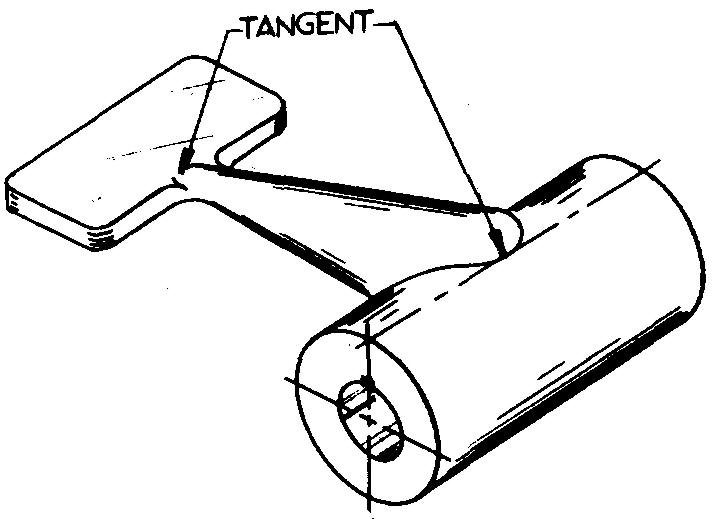
Sheet Size 8-1/2x11
Drawing Scale Half
Material Gray Cast Iron
Pieces per Unit 1
Casting Process Sand Casting Finished Surfaces Hub ends only Required Finish Symbol V
References Sees. 8 (Fig. 8-4), (Figs. 8-21 and 8-22), 12 (Fig. 12-48), (Fig. 12-68) and (Hub; Fig. 12-71); Table 49
A revolved-sectional view is required. Hub —2 dia x4 lg Hole — 5/8 ream
Foot pad — 5/16 thick x 1-1/2 wide x 3 lg, coarse knurl top surface (as cast)
Distance from center of hub to end of foot pad - 8"
Cross section of lever arm — cylindrical
Install a keyway for a 3/16 gib-head tapered key
Fillets 1/4 R
problem 14-33 hinge
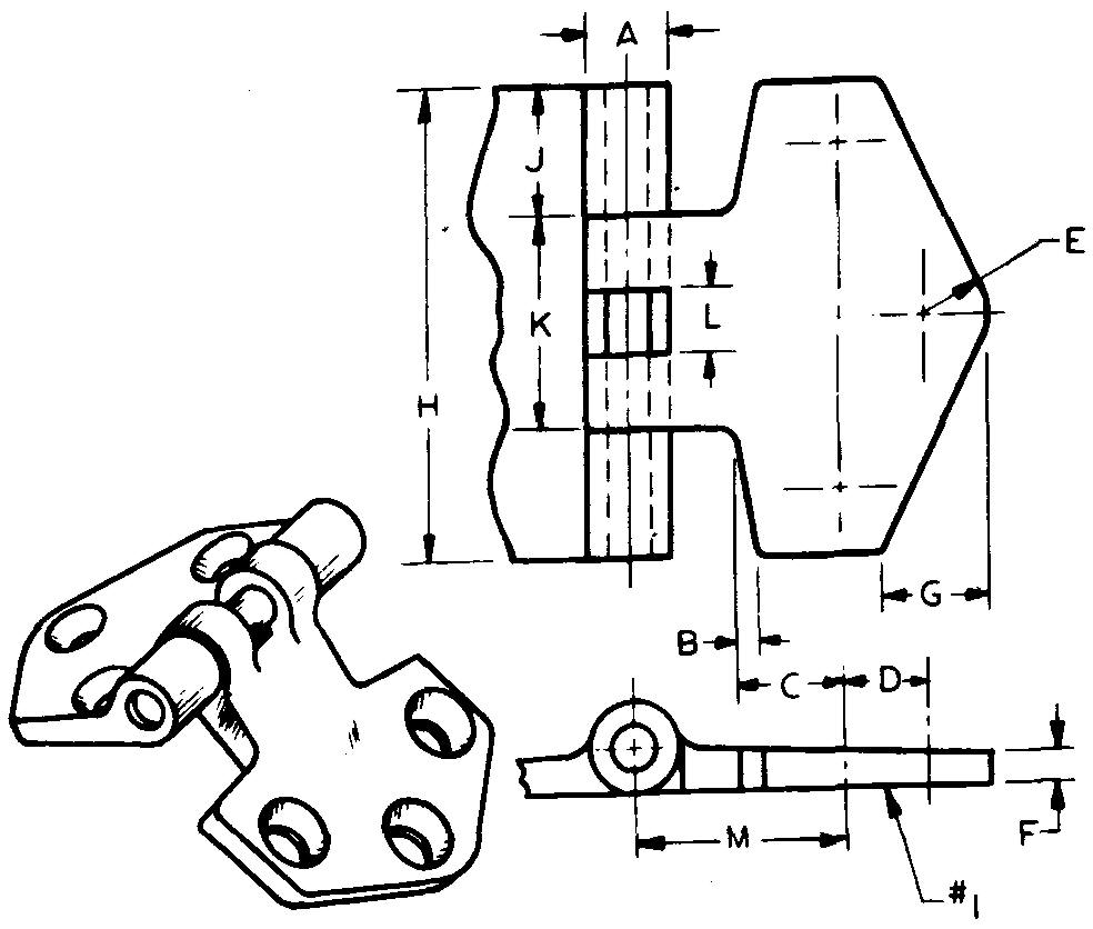
Sheet Size 8-1/2x11
Drawing Scale Optional
Material Bronze
Pieces per Unit 4
Casting Process Sand Casting Finished Surfaces #1 and dimensions L and K Required Finish Symbol f
References Sees. 8 (Figs. 8-21
and 8.22), (Power Brushing; Fig. 8-25), 11 (Interference Allowance),
11,12
(Fig. 12-13), and (Fig. 12-48); Table 15 Power brush finish.
Draw views of both leaves on the same sheet.
A — 1 /2 dia
B — 1/8
C — 5/8
D — 1/2
E — 3/8 R
F — 3/16, top taper 5°
G — 5/8
H — 2-3/4
J — 3/4
K — 1-1/4
L — 3/8
M — 1-1/4
Clearance drill and countersink holes to fit 5/16 flathead machine screws, locate outer holes 2 apart.
Pinhole — ream with .001 clearance allowance for .249/.248 dia pin
problem 14-34 cover
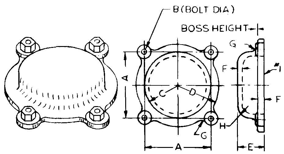
Sheet Size 8-1/2 x 11
Drawing Scale Optional
Material Bronze
Pieces per Unit 1
Casting Process Sand Casting
Finished Surfaces #1 and boss surface
Required Finish Symbol f
References Sees. 8 (Figs. 8-21 and 8-22) and (Power Brushing; Fig. 8-25)
Power brush finish.
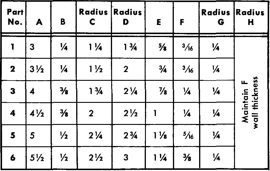
Draw Parts 1 through 6 as directed.
Select a suitable boss diameter. Boss height — 1/8
problem 14-35 frame
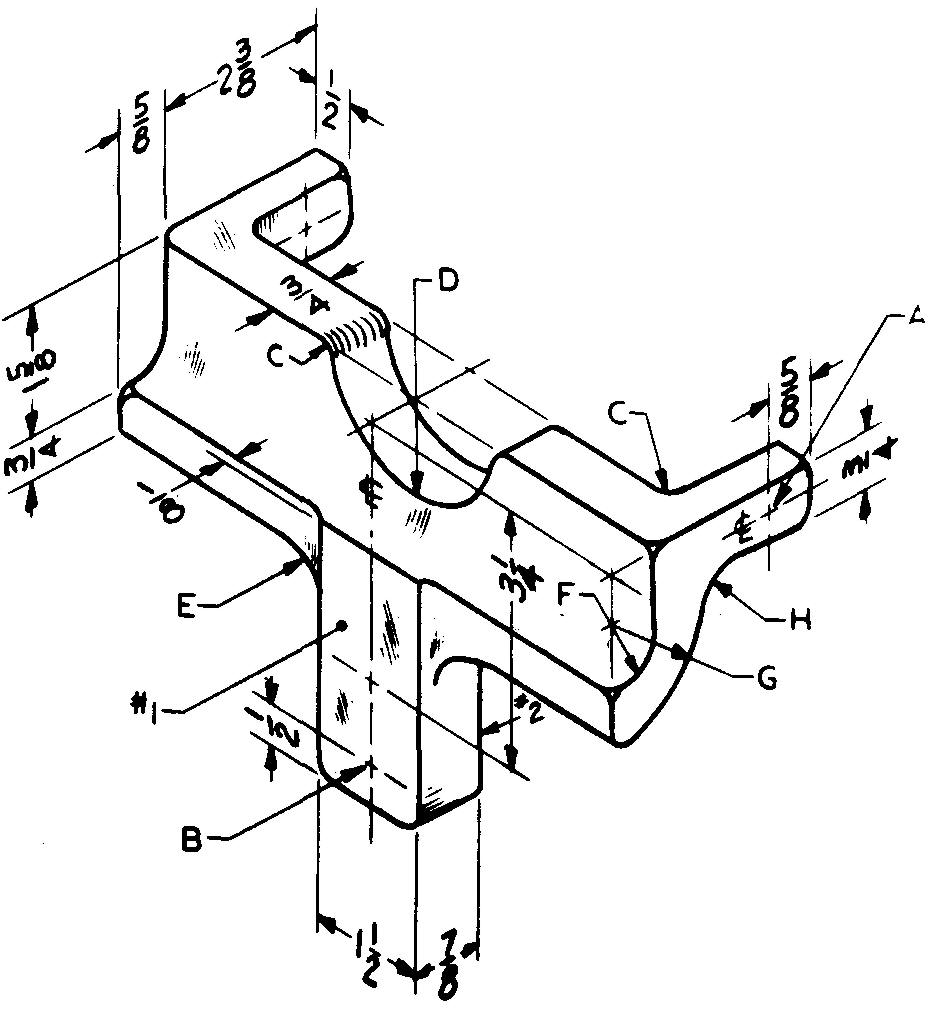
Sheet Size 11x17
Drawing Scale Optional
Material Aluminum #195
Pieces per Unit 1
Final Part Size 7-1/2 lg
Casting Process Sand Casting
Finished Surface #1
Required Finish Symbol V
References Sees. 8 (Figs. 8-21 and 8-22), 12 (Fig. 12-4), and (Fig. 12-48)
A — 3/8 ream, 2 required in line
B — Clearance drill for 3/8 bolts, 2 required locate 1-1/8 apart
C — 1/4R
D —1-1/4 R
E — 1"R
F — 5/8 R
G - 1-3/8 R
H - 1/2 R
Blend surface §2 and radius G with a 1/2 R arc and dimension accordingly.
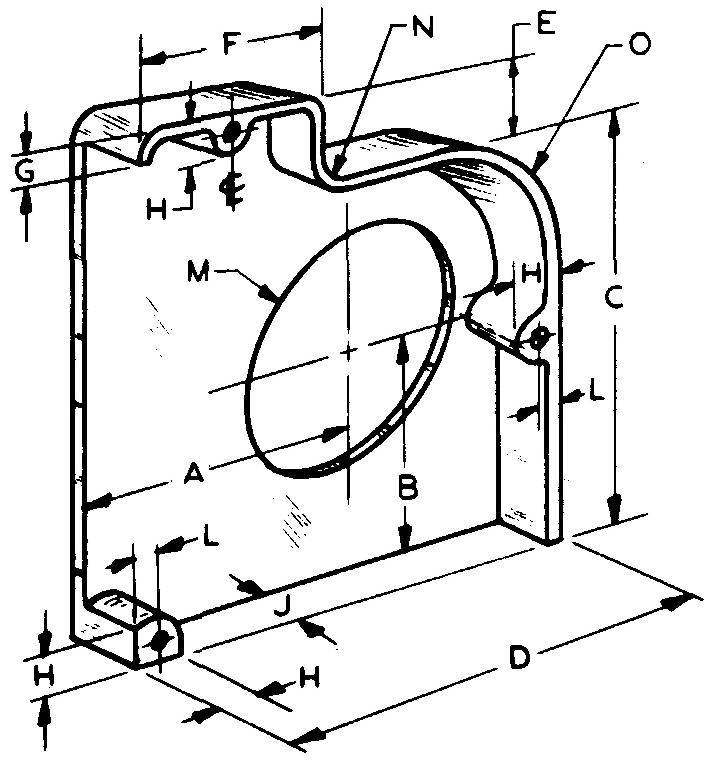
problem 14-36 gear casing
Sheet Size 11x17
Drawing Scale Full
Material Zamak #3
Pieces per Unit 2
Casting Process Die Casting
References Sec. 12 (Fig. 12-42); Table 8
A — 4
B — 3
C — 6-1 /2
D — 7-1 /4
E — 1 -3/4
F — 3-3/4
G — 1/2
H — 7/8
J — 1-1/2
L — 1 /2 (typical)
M — 3-3/4 dia
N — 1"R
O — 2R
Holes - 1/4-20 UN?-2, 3 required, 5/8 deep
Wall thickness — 1/4
problem 14-37 pulley
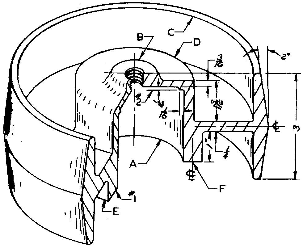
Sheet Size 11x17
Drawing Scale Full
Material Gray Cast Iron
Pieces per Unit 2
Final Part Size 6 OD
Casting Process Sand Casting
Finished Surfaces #1, #2, and crown
Required Finish Symbol f
References Sees. 8 (Figs. 8-21
and 8-22), 11, 12 (Fig. 12-6), (Fig. 12-42), 12 (Crown; Fig. 12-74), and 20
(Fig. 20-11);
Tables 8 and 68
A full-sectional view is required. Specify "Fillets and rounds — 1/8 R."
A — 2-1/8 dia bore, tolerance +.0005, -.0000
B — 1-1/4 dia
C — 5-1/2 dia
D — 2-3/4 dia
E — 3-1/8 dia
F — 1/4-20 UN?-2 threads, 5/8 deep, 4 required, equally spaced on 2-5/8 BC Center hole — To fit 1/4 NPT
problem 14-38 battery terminal assembly
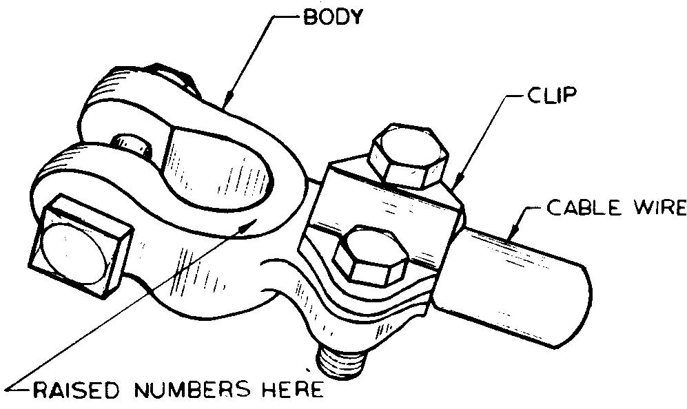
Sheet Size 8-1/2 x 11
Drawing Scale Full
Material Lead Total
Pieces Required 6 500
Casting Process Die Casting
References Table 13
Two details: 1) Body. 2) Clip. Draw views of both details on one sheet.
Specify "Body should be cast with raised numbers:
LK — 4385; give location dimension for the letter L;
each raised letter and number to be approximately 1/8 square by 3/64 high."
Estimate all omitted sizes and proportions.
The battery terminal (not shown) is 5/8 dia at large end and tapers 3° on a side.
Distance from the center of the terminal to the center of the 1/4 square-head bolt and nut — 1/2
Distance from the center of the terminal to the center of the 1/4-20 UN7-1 hexagonal-head bolts - 1-1/2
Bolts spaced 1" apart
Cable wire dia — 5/16
problem 14-39 end cap
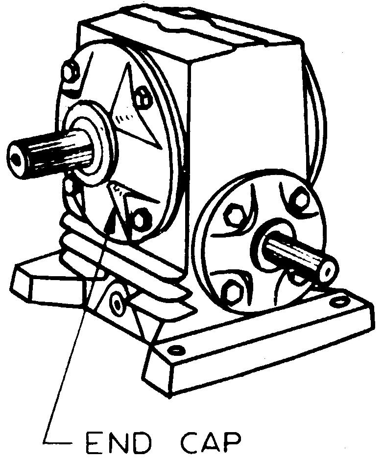
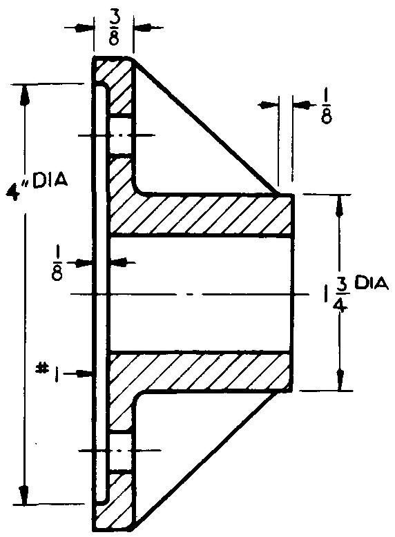
Sheet Size 8-1/2x11
Drawing Scale Full
Material Gray Cast Iron
Pieces per Unit 1
Final Part Size 4-1/2 OD x 1-7/8 lg
Casting Process Sand Casting
Finished Surface #1
Required Finish Symbol V
References Sees. 8 (Fig. 8-21 and 8-22), 11, 12 (Fig. 12-25), and (Fig. 12-28), Tables 6 and 13.
Barrel finish before machining
Spotface the four equally spaced clearance holes on 3" BC, for 1/4 hexagonal cap screws
Ream center hole to 1 -1/8 dia, tolerance +.001, -.000
The rib sides are parallel and are formed by swinging 1/2R arcs from cap screw hole centers.
problem 14-40 pressure plate
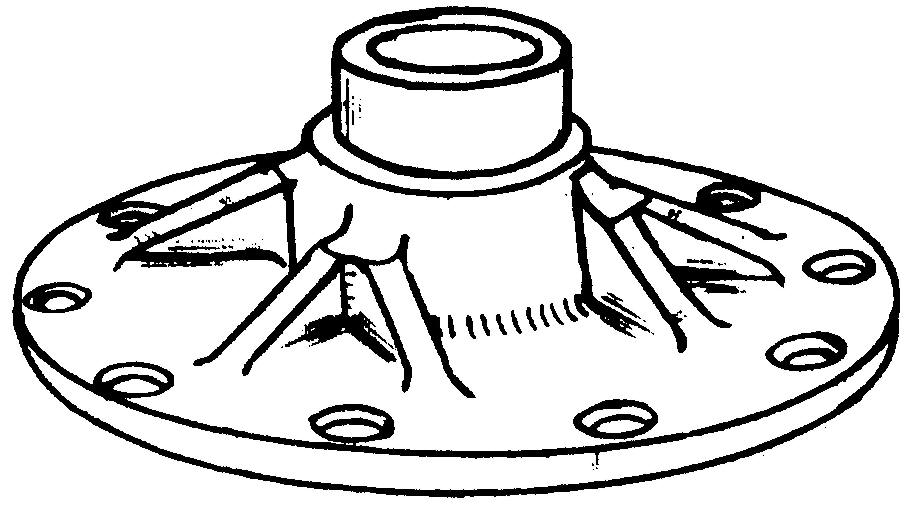
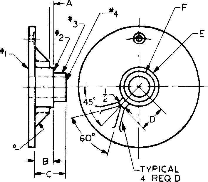
Sheet Size 11x17
Drawing Scale Full
Material Ductile Iron
Pieces per Unit 1
Casting Process Sand Casting
Finished Surfaces #1, #2, #3, and #4
Required Finish Symbol V
References Sees. 8 (Figs. 8-21 and 8-22), 11, 12 (Fig. 12-25), and 12 (Flange; Fig. 12-70); Table 14
Specify "Center hole must be concentric with 1-3/4 dia within ±0.002 T.I.Ft."
A — 1/4
B — 1-1/8
C — 1-7/8
D —1-1/2
E — 2-1 /4 dia, tolerance -.002, -.003
F — 1-3/4 dia, tolerance ±.0005
Flange — 7-1/4 dia x 3/8 thick
Center hole — 1-1/4 dia, tolerance +.0005
Holes — 13, equally spaced on 6-1/8 BC
clearance drill and spotface for 1 /4 socket-heac cap screws
problem 14-41 bobbin chute
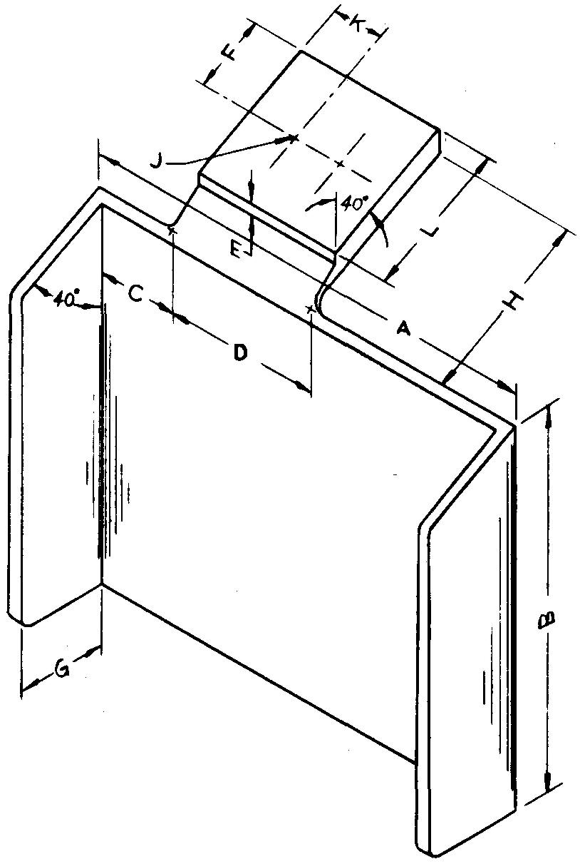
Sheet Size 11x17
Drawing Scale Full
Material Aluminum #13
Pieces per Unit 1
Casting Process Die Casting
References Sec. 12 (Fig. 12-42); Tables 6 and 8 Annodize finish.
A — 9
B — 7 (to sharp corner)
C — 1-1/2
D — 3
E — 3/16 (vertical measurement)
F — 1-1/2
G — 1-3/4
H — 3-3/4
J — 3/8-16 UN?-2 threads, through, 2 required, locate 1" apart
K — 1"
L — 3
Top pad — 3/4 thick with two 1/4 thick supporting ribs (not shown) on back surface (location and size to suit)
Walls — 1/4 thick
problem 14-42 cross slide
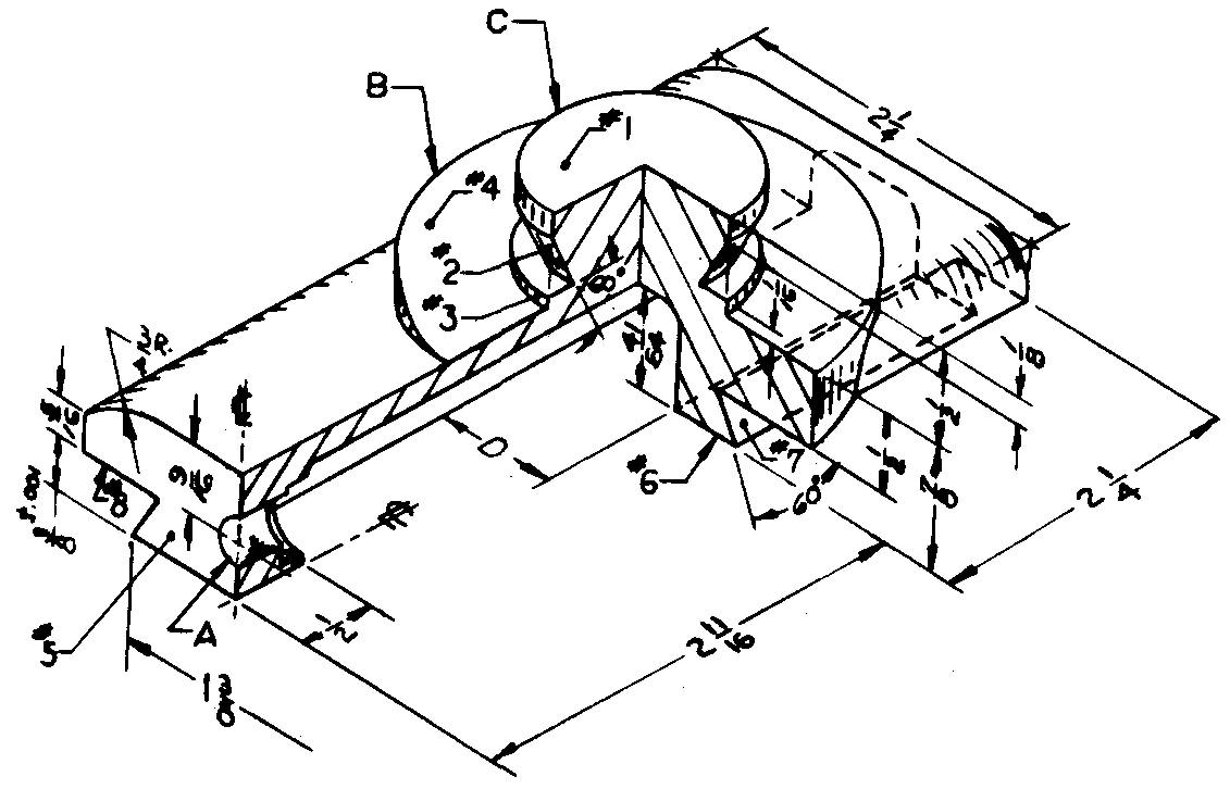
Sheet Size 8-1/2 x 11
Drawing Scale Full
Material Gray Cast Iron
Pieces per Unit 2
Casting Process Sand Casting
Finished Surfaces #1 through #8
Required Finish Symbol f
References Sees. 8 (Figs. 8-21 and 8-22), 10, 11, and 12 (Fig. 12-19)
A full-sectional view is required.
Calculate and specify over rolls dimensions (0.250 dia rolls) for dovetail.
A — 5/16 drill, 1/2 dia reverse counterbore, 1/8 deep
B — 2-1/2 dia
C — 1-1/4 dia
D — Center slot 5/8 wide
problem 14-43 drill head
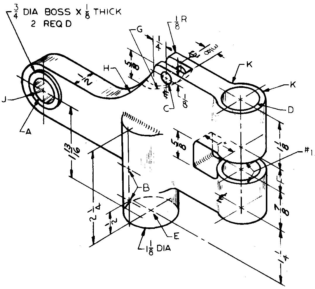
Sheet Size 11x17
Drawing Scale Full
Material Gray Cast Iron
Pieces per Unit 1
Final Part Size 4-5/16 lg
Casting Process Sand Casting
Finished Surfaces #1, slot, and boss ends
Required Finish Symbol f
References Sees. 8(Figs. 8-21 and 8-22), 11 (Interference Allowance), (Fig. 12-4), 12 (Fig. 12-48), and 13 (Milling; Fig. 13-8)
A — 1/2 ream through
B — 1/8 drill through, 2 required, locate 3/4 apart
C — 1/8 drill, 2 required in line
D — 3/4 dia bore, tolerance +.0015, -.0005, 2 required in line
E — 5/8 ream, 2 deep
F — To fit .500/.499 thick mating part with .0015 clearance allowance
G — 7/8 R cutter, 1/8 wide (central with 1/2 dimension)
H — 1-1/2R
J — 9/16R
K — 1/2R
Hole locations:
From hole A to hole D —6
From hole E to hole D — 3
From hole C to hole D — 2
problem 14-44 gear guard
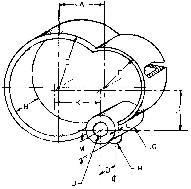
Sheet Size 11x17
Drawing Scale Optional
Material Zamak #5
Pieces per Unit 2
Casting Process Die Casting
References Sees. 11 and 12 (Fig. 12-42); Table 8
A — 5
B — 1-7/8
C — 1/4
D — 1 -1/4 (to center line of boss H)
E — 4R
F — 3R
G — 2 dia x 2-1/2 lg
H — 1-1/8 dia boss, 5/16-18 UN?-3 threads to hole J
J — 1" dia hole, tolerance +.001, -.002
K — 3-3/8
L — 2-15/16
M — 1-1/4 (to end of boss H)
Wall thickness — 1/4
problem 14-45 bracket
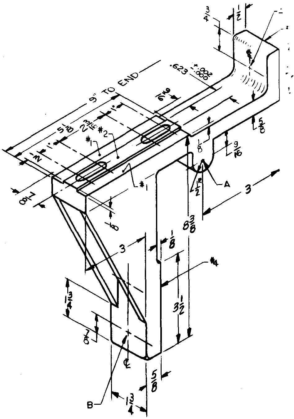
Sheet Size 11x17
Drawing Scale Optional
Material Gray Cast Iron
Pieces per Unit 2
Casting Process Sand Casting
Finished Surfaces #1, #2, #3, #4, and 0.623 dimension
Required Finish Symbol V
Heat Treatment Stress relieve
References Sees. 8 (Figs. 8-21 and 8-22), 9, 11, 12 (Fig. 12-25), and (Fig. 12-48); Table 14
A — 5/8 ream, 2 required
B — Clearance drill and spotface for 5/16 socket-head cap screws, 2 required, locate 1-3/4 apart
Slots — Clearance to fit 5/16 bolts Ribs - 1/4 thick
problem 14-46 bearing cap
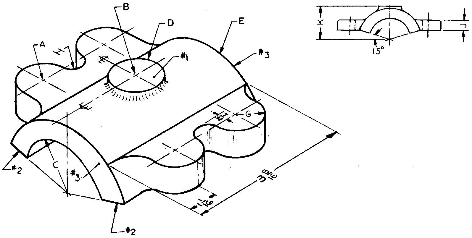
Sheet Size 11x17
Drawing Scale Full
Material Brass
Pieces per Unit 1
Casting Process Sand Casting
Finished Surfaces #1, #2, and #3
Required Finish Symbol f
References Sees. 8 (Figs. 8-21 and 8-22), 11, 12 (Fig. 12-25), and 20 (Fig. 20-11); Tables 28, 34, and 68
Specify "Fillets and Rounds — 1 /8 R."
A — Clearance drill for 3/8 dia studs and spot-face for plain washers, vertical holes, 4 required locate 1-7/16 and 3-1/4 center to center
B — 1/8 NPT
C — 1-13/16 dia, tolerance +.0015
D — 1"dia
E— 2-3/4 dia
G — 9/16 R
H — Blend radius
J — 1/2
K — 1-1/2
problem 14-47 apron
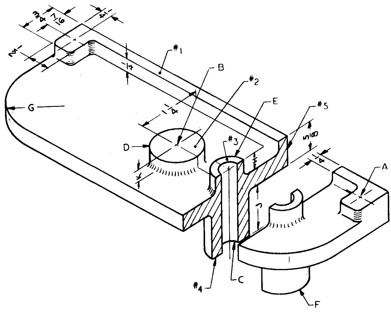
Sheet Size 11x17
Drawing Scale Full
Material Cast Iron
Pieces per Unit 1
Final Part Size 2-13/16 wide x 6-3/8 lg
Casting Process Sand Casting
Finished Surfaces #1, #2, #3, #4, and #5
Required Finish Symbol V
References Sees. 8 (Figs. 8-21 and 8-22), 10, 12 (Fig. 12-42), and (Fig. 12-48); Tables 4 and 8
Calculate and specify the total weight. Disregard fillets and rounds.
A - 1/4-20 UN?-3 threads, through holes, 2 required
B — 5/8 ream through
C — 7/16 ream through
D — 1" dia, locate on common center line 1 -1 /4 from E
E — 3/4 dia, locate 1-9/16 from surface #5 and 1 -1/4 from near end
F - 1" dia G - 1 -1 /4 R, both ends
H-3/8 J-1"
K — 3/8 (top boss only)
