Forming parts by fabricating
Introduction
The word fabrication as used in industry usually refers to the processes involved in manufacturing and fastening together the various pieces which make up a complete part. The processes in the manufacture of metal parts by fabrication differ greatly from casting, machining, or forging processes.
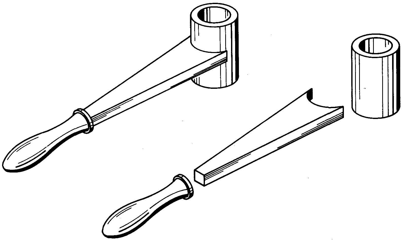
Figure 16-1 shows the pieces which are required to fabricate a handle. The various pieces of the handle have been separately machined or cut from stock. They are assembled by welding.
Fig. 16-1. a fabricated handle
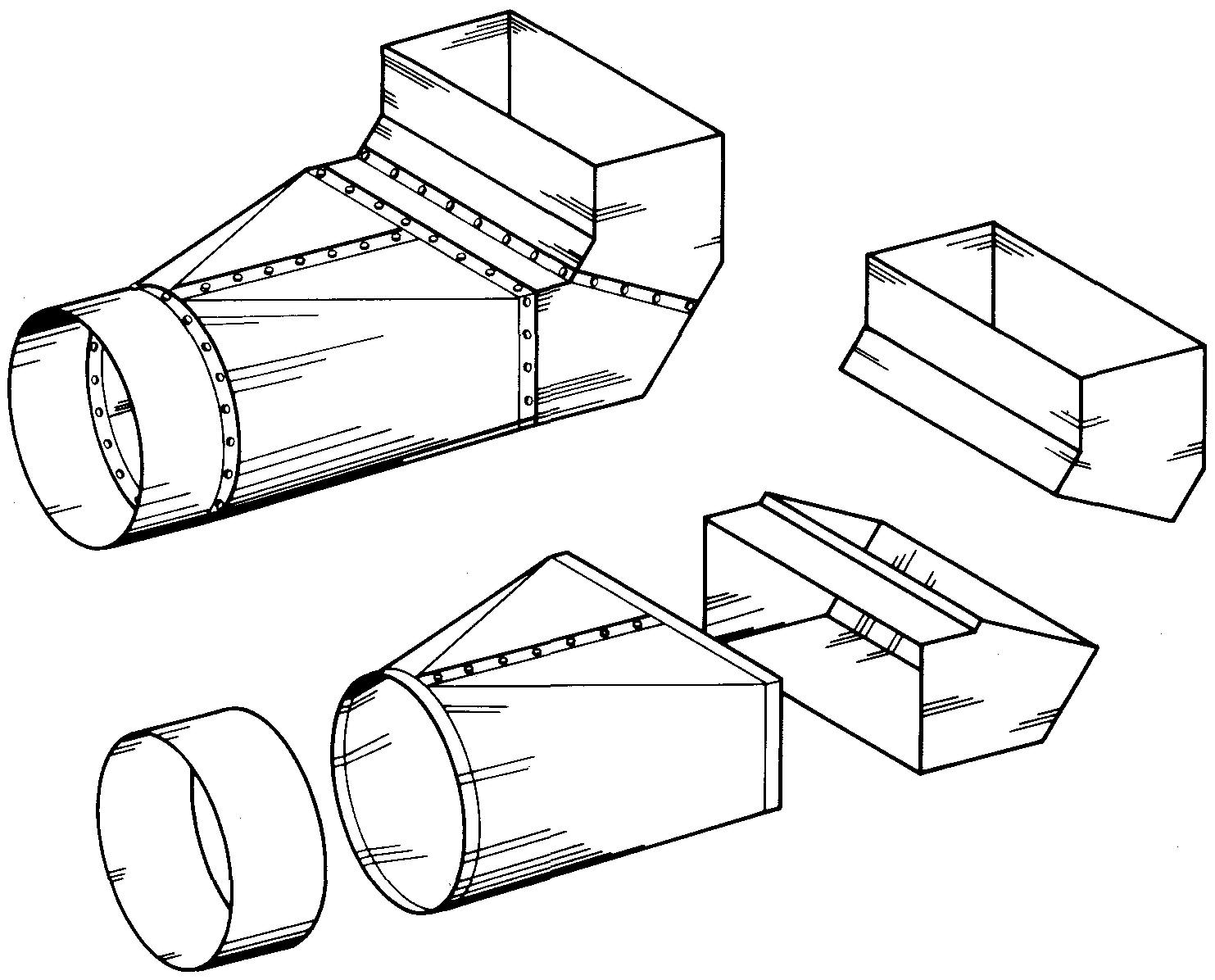
Figure 16-2 shows the pieces of a furnace fitting. Each piece is separately cut and formed to shape from sheet-metal stock and then assembled by using special joints and rivets.
Fig. 16-2. a furnace fitting
Often parts made of sheet-metal pieces are fastened together by welding.
Welding drawings
Welding is the process of permanently fastening metal pieces together to form a complete part. It is used not only to join individual pieces but also to assemble groups of previously assembled parts.
In the manufacture of leakproof containers, for example, welding has almost entirely replaced the use of rivets and bolts. It is fast gaining favor in many industries for producing complicated machine parts which were formerly made by casting, machining, or forging.
Since welding requires no previously made wood pattern, die, or mold, it is considered a fast and relatively simple process.
In comparing the production of welded parts to those made by casting or forging, one finds that welding often results in a substantial saving of time and expense. In most cases, welded parts weigh less than cast or forged parts. Little, if any, sacrifice in strength is made.
Common metals which can be successfully welded include cast iron and steel, iron and steel alloys, brass, copper, aluminum, magnesium, and many other metals. Many dissimilar metals such as brass and steel, or cast iron and steel, and so on can be joined by welding.
Examples of welded construction are not hard to find. Buildings, bridges, towers, ships, and farm equipment have been produced by welding for many years.
Other applications include automobile and truck frames and bodies; railway rolling stock and equipment; industrial machinery; heating and ventilating ducts; aircraft; and containers for oil, gasoline, water, and other liquids.
Practically every industry uses welded construction in making parts or uses equipment that has been made by welding.
Due to the increased use of welding, the study of welding practice has become increasingly important to the machine draftsman in recent years. He must know how to show correctly on a drawing the shape and size of the pieces to be welded. He must also know how to specify to the welder the type, size, shape, and, often, the strength requirements of a welded joint.
As for parts made by other processes, specifications for machined holes or slots, finished surfaces, and so on must also be given on the drawing.
Welding drawings must be carefully prepared. The methods of welding and the welding symbols which follow should be carefully studied to ensure that the proper weld symbol which is related to the desired weld is shown on the drawing.
Methods of welding
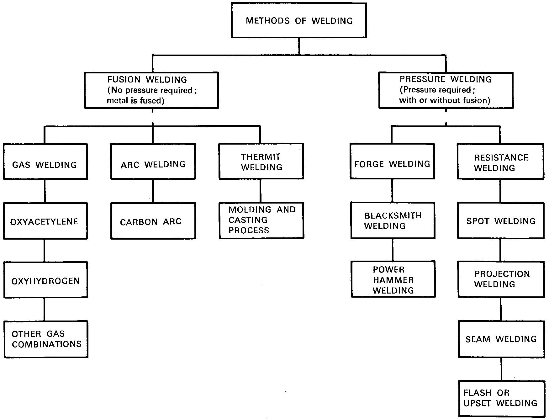
The principal methods of welding are fusion welding and pressure welding. Each of these methods includes a wide variety of welding processes, as listed in Fig. 16-3.
Fig. 16-3. methods of welding
Fusion welding
The process of joining metal pieces together by heating them to a melting temperature is called fusion welding. Frequently extra molten metal is added. The molten metal forms a joint when cooled. The heat is created by gas welding, arc welding, or thermit welding.
Gas welding is done by igniting a mixture of two gases, usually oxygen and acetylene (oxyacetylene welding) or oxygen and hydrogen (oxyhydrogen welding).
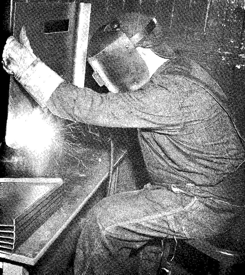
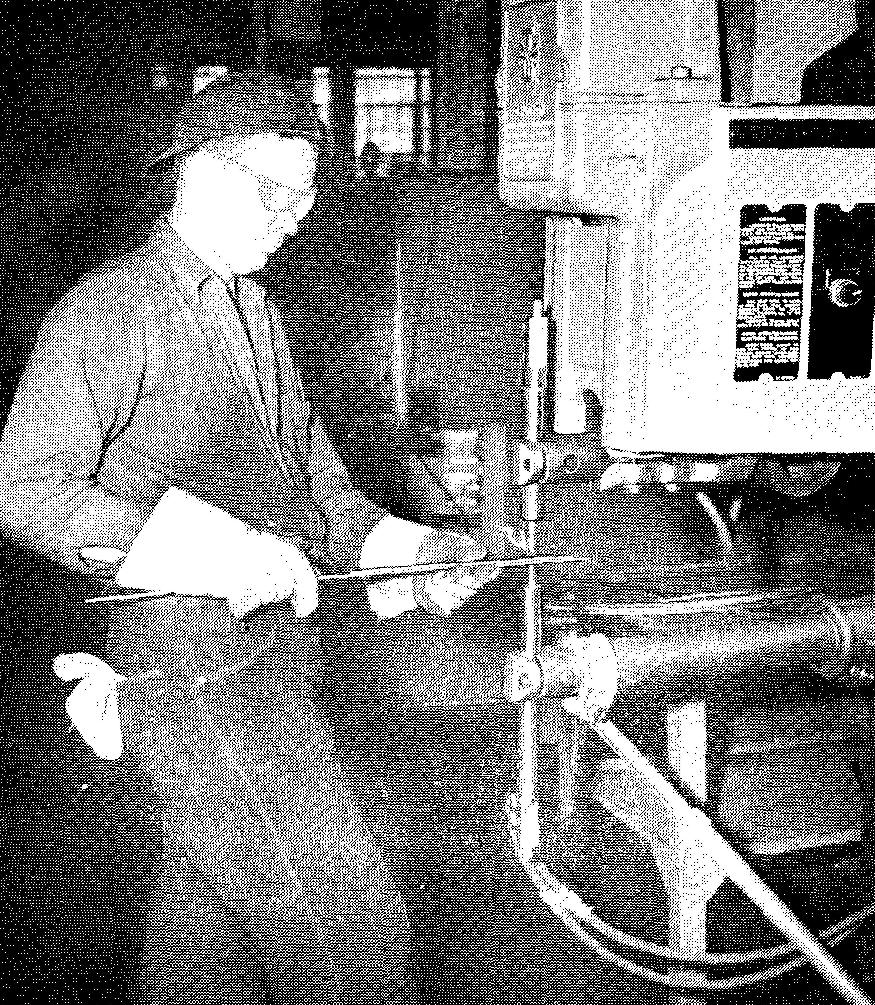
Arc welding, shown in Fig. 16-4, is done with an electric arc which supplies the necessary heat.
Fig. 16-4. Arc welding
Thermit welding is done by igniting a mixture of aluminum and iron oxide which burns at a high temperature. The burning mixture releases molten iron which fuses with the pieces to be joined and forms a welded joint upon cooling.
Pressure welding
Joining metals by heating and forcing them together under mechanical pressure or, more simply, by heating and squeezing is called pressure welding. While this can be done in many ways, it is most commonly done by forge welding or by resistance welding.
Forge welding is the process of
heating the pieces and then forming the joint by pressure or by repeated blows
from a hammer.
Resistance welding is the process of applying an electrical
current to metal pieces.
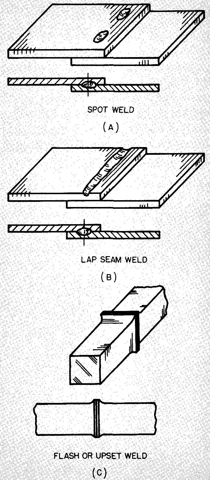
This method builds up sufficient heat to permit joining the pieces under pressure. Spot welding, shown in Fig. 16-5; projection welding; seam welding; and flash, or upset, welding are included in the category of resistance welding.
Fig. 16-5. spot welding
Basic types of joints
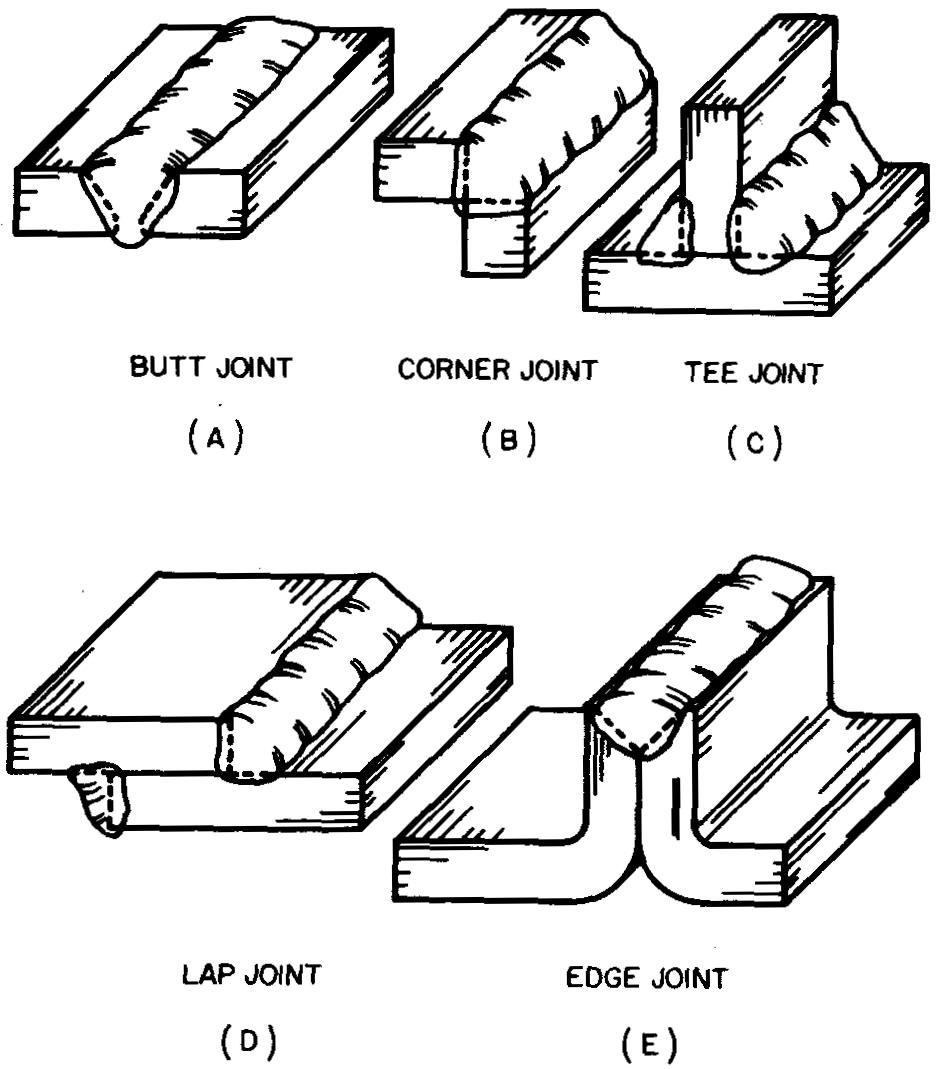
The region in which metal pieces in contact are welded is called a joint. There are five basic types of joints, and it is important for the draftsman to know and to recognize them.
There are many variations of each joint, depending upon the thickness of the pieces to be joined, the strength requirements, and so on. Figure 16-6 will aid the draftsman in identifying and selecting types of joints.
Fig. 16-6. Five basic types of welded joints
Basic types of welds
The basic types of fusion welds are shown in Fig. 16-7. The basic types of pressure welds are shown in Fig. 16-8.
Fig. 16-7. Basic types of fusion welds
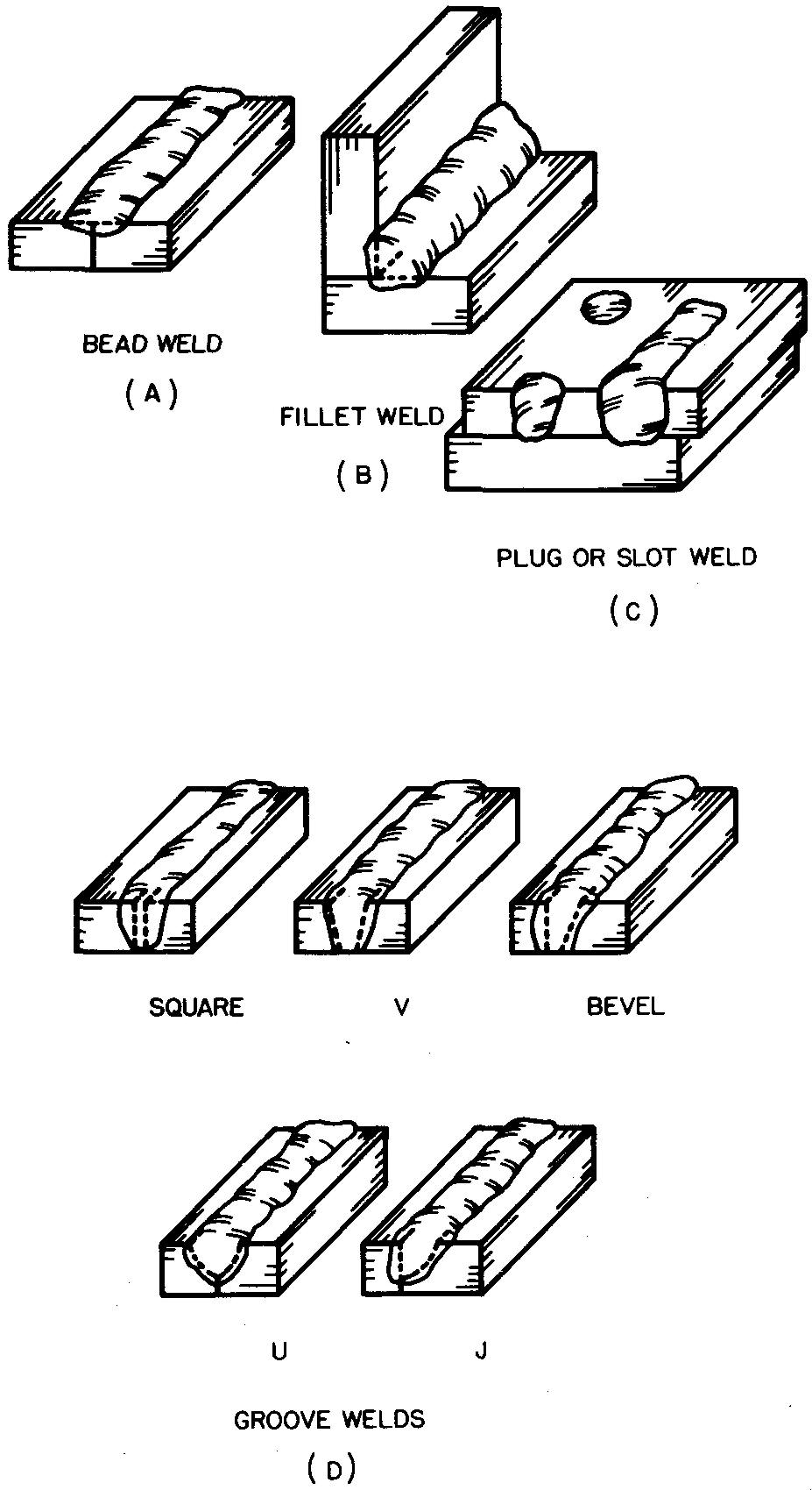
Fig. 16-8. Basic types of pressure welds
Welding symbols
The desired types of joints and welds must be specified on each drawing.
It would be very tedious and time consuming to draw each type of joint and weld. This is especially true for structures which are assembled entirely by welding and which require many different kinds of joints, each requiring a great deal of information.
A system has been devised which eliminates the need for the draftsman to draw the actual joint or weld each time it appears on a drawing.
The welding symbol which is used to specify a weld can be roughly compared to a note and a leader. Instead of a written description as in a note, the entire information is given in the form of symbols, letters, and marks.
These are placed near the portion of the symbol called the reference line. The leader, or reference line, consists of an arrow which points to the joint where the weld is to be made.
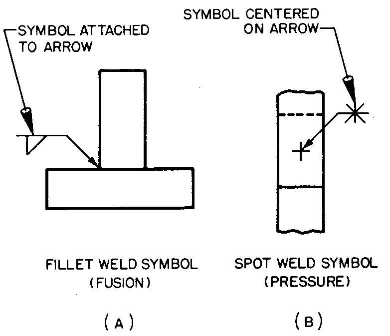
The type of weld desired is shown by a symbol, which for fusion welding is drawn attached to the arrow.
For pressure welding, the symbol is centered on the arrow. Figure 16-9 shows the standard symbols for the various types of welds. Figure 16-10 shows how the symbol for each weld is applied to the arrow.
Fig. 16-9. Symbols for types of welds
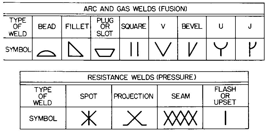
Fig. 16-10. How symbols are applied to the arrow
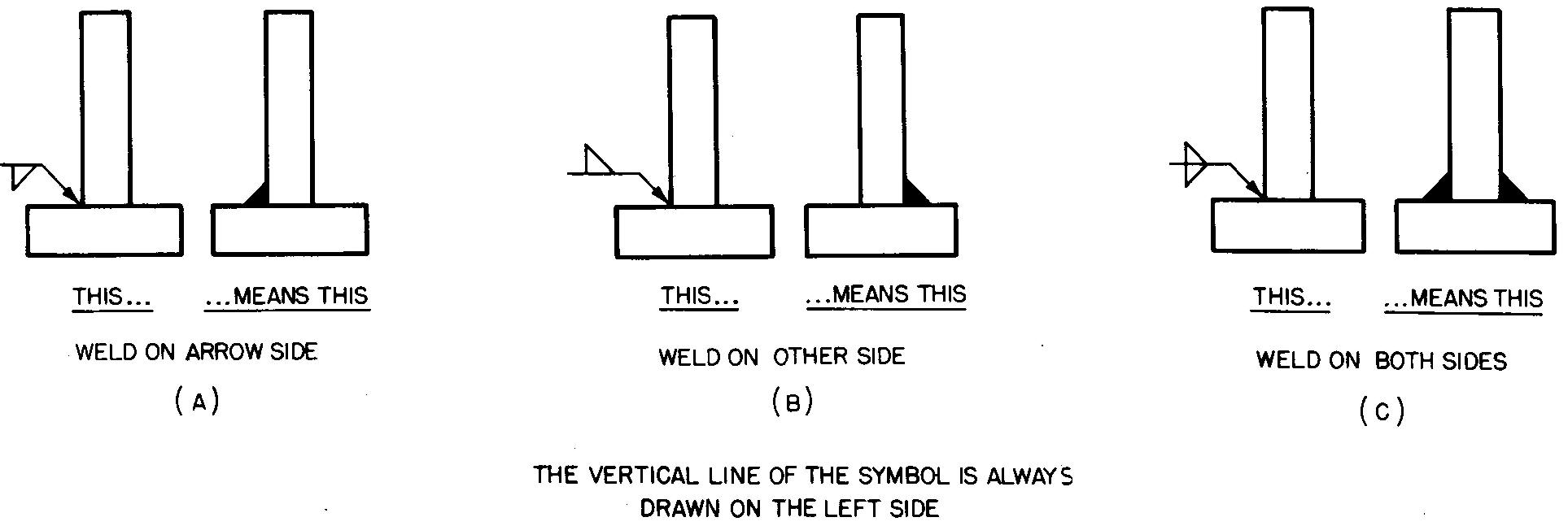
The placement of the welding symbol on the arrow for fusion welding is important. For example, the vertical side of a fillet symbol must always be drawn on the left.
The placement of the symbol on the arrow indicates the required side on which the weld is to be made. Figure 16-11 illustrates this principle for fillet welds.
Fig. 16-11. Placement of gas and arc weld symbols on the arrow
Symbols for pressure welding are always centered on the arrow (Fig. 16-10B) and are not drawn above or below the reference line. Since the weld is always made between the two parts, the position of the weld is obvious.
Thus the need for drawing the symbol above or below the reference line is completely eliminated.
The complete welding symbol is shown in Fig. 16-12. The legend below explains the numbers which are drawn to the various elements of the symbols.
A complete treatise covering all phases of the welding symbol may be found in the booklet entitled Welding Symbols by the American Welding Society, 33 West 39th Street, New York, or in ASA Y32.2-1959 American Standard Graphic Symbols for Welding.
Fig. 16-12. The complete welding symbol
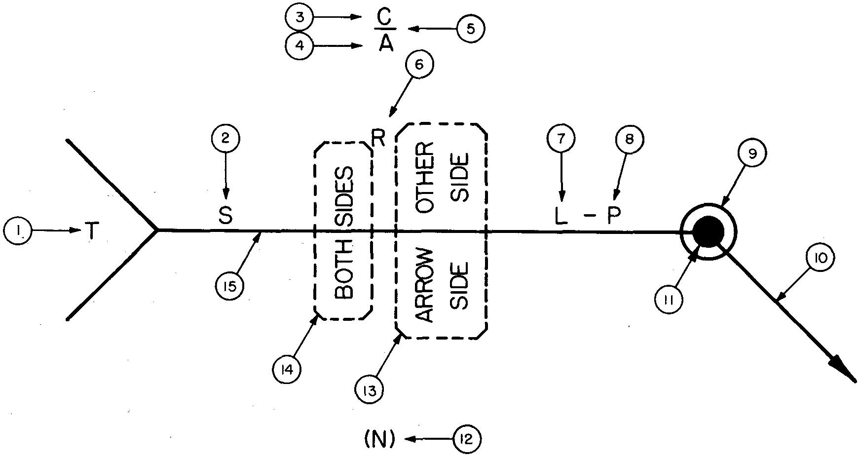
LEGEND OF THE WELDING SYMBOL
1 Code Letter — Used to specify information not otherwise given on the symbol. A general note explaining the code letter should always be placed on the drawing. If the reference is not used, both the code letter and the entire tail of the symbol is omitted.
2 Specifies the size and strength of pressure welds. Strength is measured in units of 100 pounds per weld, 100 pounds per linear inch, or 100 pounds per square inch. The size is always given in hundredths of an inch, as shown in Fig. 16-13.
3 Specifies the type of finish of the weld. C is chip, G is grind, and M is machine.
4 Specifies the included angle of the countersinking operation (shown in Fig. 16-15) for plug welds.
5 Specifies the final or
finish contour of the weld, as shown in Fig. 16-14. If the weld is to be
finished flush with the surface of the piece, it is indicated as —. If the weld
is to be finished with a convex shape, it is indicated as
 .
.
6 Specifies the size of the root opening for plug and slot welds, as shown in Fig. 16-15B. The angle and size (usually given as a fractional part of an inch) is given.
7 Specifies the length (see Fig. 16-13C) of the weld in inches.
8 Specifies the pitch (or the center to center dimension) for the spacing of non continuous welds, as shown in Fig. 16-13B.
9 Specifies welds which extend completely around the joint, as shown in Fig. 16-16.
10 Arrow connecting the reference line to the arrow side of the joint, to grooved member, or to both.
11 Specifies a field weld (see Fig. 16-17) which is the term used to describe a joint made in the field or at the location where the parts are to be finally assembled. This notation applies to cases where the weld would not be made in the shop.
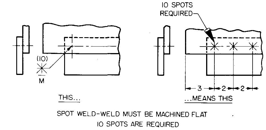
12 Specifies the quantity of spot or projection welds, as shown in Fig. 16-18.
13 and 14 Basic weld symbol indicating the type and position of the desired weld, as shown in Fig. 16-11.
15 Welding symbol reference line shows data on size, strength, type, position, length, and pitch.
Only those symbols, letters, and marks as are actually required are used to describe the particular weld on a drawing. That is, it is not necessary in every case to use the entire welding symbol.
Welding symbols should be drawn mechanically (not freehand). All of the elements should be carefully applied to the symbol so that a clear idea of what is required is given. Commercially available templates may be used, which simplify and speed up the drawing of symbols.
Identification of welding symbols
Figures 16-13 through 16-18 show examples of various welding symbols. In each case the elements of the symbol are explained. After a period of time, most draftsmen learn to identify at sight the more commonly used welding symbols.
Fig. 16-14. Identification of welding symbols
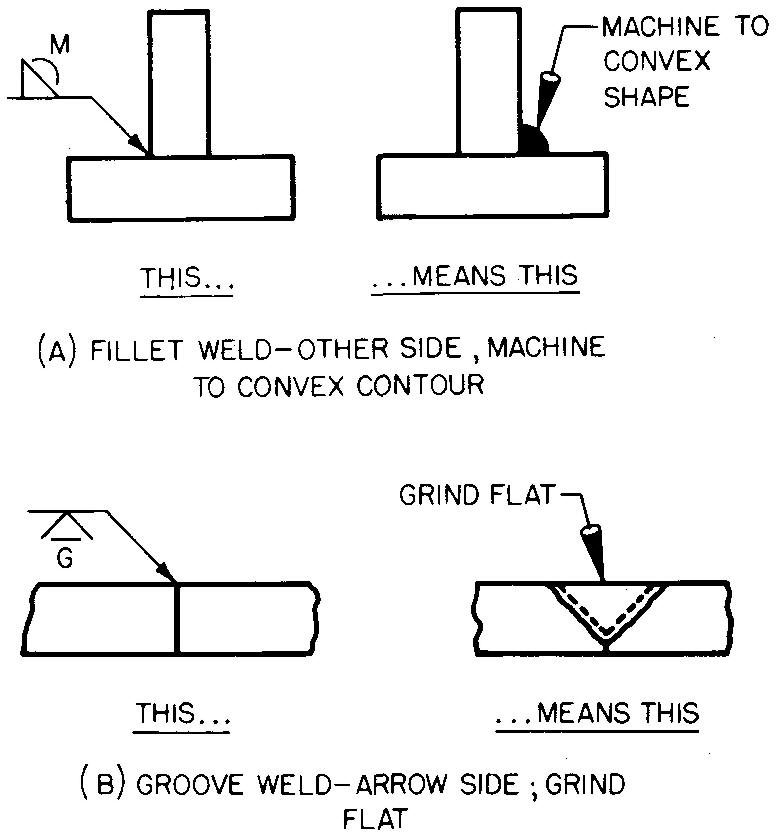
Fig. 16-15. Identification of welding symbols
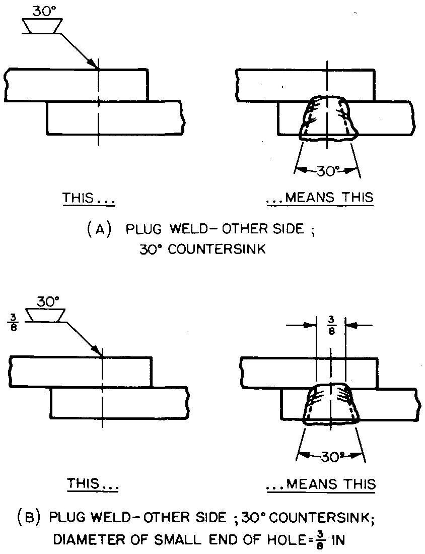
Fig. 16-16. Identification of welding symbols
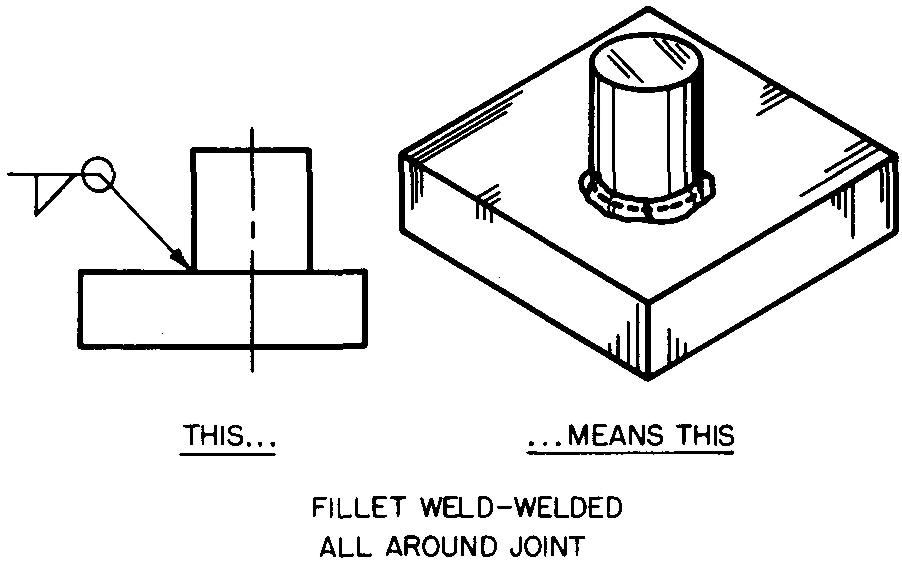
Fig. 16-17. Identification of welding symbols
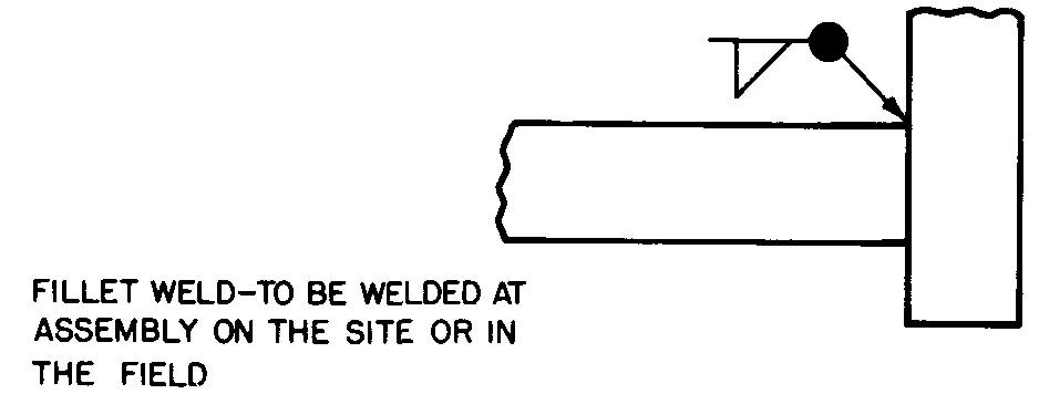
Fig. 16-18. Identification of welding symbols
Welding drawing practices
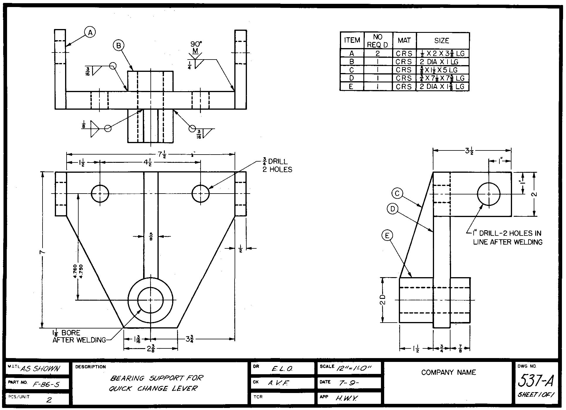
Figure 16-19 shows a typical welding drawing in which the welding symbol is used several times.
Fig. 16-19. A typical welding drawing
There is only a slight difference in the way a machine draftsman prepares a welding drawing from the way he prepares a drawing of a part which is to be cast.
One difference is that parts made by welding are usually drawn to show all of the pieces assembled. The welding symbol is used to show the complete specification of each joint. It is important that each piece of the welded assembly of parts be fully dimensioned so that the pieces may be cut from standard size stock.
Most operations such as slots and keyways or drilled, threaded, or reamed holes are generally performed after the individual pieces have been welded together.
Many companies require a parts list, which is also shown in Fig. 16-19. The parts list simplifies the process of ordering stock for each piece of the welded assembly.
Sheet-metal drawings
Sheet metals are relatively thin metals which measure roughly 1/2 inch or less in thickness. More and more uses are being found today for industrial, commercial, and military articles of sheet metal. Sheet-metal products are found in practically all industries.
The building industry uses sheet-metal parts for roofing and skylights and for heating and air conditioning parts. Ship and boat building, aircraft, railroad, and automobile industries have been using sheet metals for many years.
Other common uses include advertising sign work; dairy and creamery machinery; and factory equipment such as benches, storage bins, lockers, cabinets, and stools.
Sheet metal is also used for household, office, school, store, and hospital furniture and equipment; television sets; stoves; refrigerators; washing machines; dryers; portable buildings; store fronts; and for a wide variety of containers such as cups, pails, pots, pans, buckets, trays, and cans.
Note the variety of shapes of the sheet-metal parts shown in Fig. 16-20.
Fig. 16-20. A variety of sheet-metal objects
From the above listing, it is evident that the machine draftsman will eventually, if not immediately, be required to prepare drawings of objects made of sheet metal.
Many machines have sheet-metal safety guards; oil and coolant tanks; trays and shelves; and other attachments which are designed and drawn especially for a particular machine. It is very necessary, therefore, for the machine draftsman to know some of the more important requirements for preparing sheet-metal drawings.
One of the chief advantages in making parts of sheet metal is that they can be easily cut to size and bent to practically any desired shape.
Also, the individual sheet-metal pieces may be readily welded or fastened together, with joints and seams, with screwed fasteners, or with rivets. By the use of brackets or projecting edges, a sheet-metal part may be readily attached to its proper location.
In order to reduce assembly problems, sheet-metal objects should be designed with a minimum number of separate pieces. Whenever possible, the sheet-metal part should be made from one flat sheet of stock and bent to the desired shape. Such a procedure is followed when a part can be bent or folded into the required shape without excess use of metal.
Sheet metals include practically all kinds of materials. The most common materials used in sheet-metal work are iron, steel, tin, copper, brass, and aluminum.
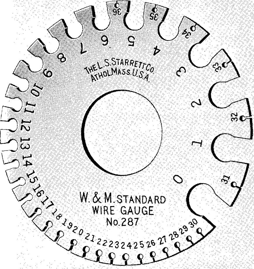
Sheet metal is made to standard thicknesses; each thickness has a gage number. Table 64 lists gaging systems for various metals and commodities. Table 65 lists the available sizes of sheet metal by gages. When one uses Table 65, it is important to look for the gage number of iron and steel in the column marked US Std or Mfrs Std.
Gage numbers of brass, bronze, copper, and all other metals (except iron and steel) must be taken from the American or from the Brown and Sharpe columns of Table 65.
There is a slight difference in the gage thickness for each column. The tables are especially useful in that they also list the gage numbers for wire as well as for sheet metal.
The diameter of #12 gage wire, for example, is the same as the thickness for #12 gage sheet metal and so on. It will be noted that the higher the gage number, the thinner the metal. Sheet-metal and wire sizes may be measured with a tool called a wire gage, which is shown in Fig. 16-21.
Fig. 16-21. A wire gage
Bend allowance
Figure 16-22A shows a piece of sheet metal which measures 4 by 4 inches. Figure 16-22B shows the same metal piece after bending 90° along the center line AB.
Fig. 16-22. Bend allowance
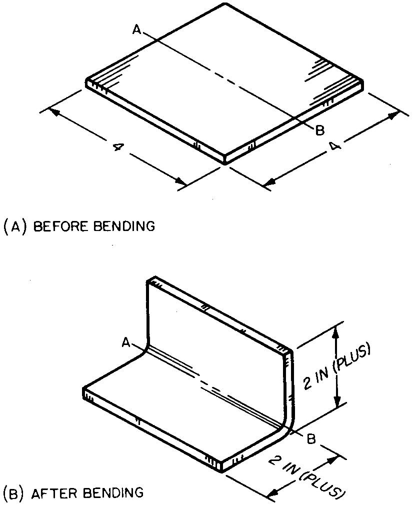
Each leg is accurately measured and found to be slightly longer than 2 inches. How is this possible?
How can a piece of metal grow longer after bending?
The answer is found by examining the manner in which the metal stretches around the radius of the bend. While the metal at the inside of the bend squeezes or crowds, the metal at the outside of the bend stretches. There is a line, approximately at the center of the two radii, which neither squeezes nor stretches. This imaginary line is called the neutral axis.
In most cases, for sheet metal of #24 US Std gage (0.025 inch) or thinner, the slight amount of distance gained by bending may be neglected. However, some companies require that bend allowance be shown on their drawings for sheet-metal parts which have been made from sheets measuring greater than #24 US Std gage.
A sheet-metal part which requires a 90° bend, #12 US Std gage (0.109 inch) for example, would be made slightly shorter to allow for the gain in size due to bending.
This gain in size is usually worked out by the sheet-metal worker, who uses special tables which take into consideration the kind of material, thickness, and the radius and angle of bend. In some cases, the draftsman must figure this gain in size. It is considered accurate enough for most purposes to take the center line length at the bend for the bend allowance, especially for bends of large radii.
In practically all cases, the draftsman may disregard allowance for bending. By custom of long standing, the amount of this allowance is usually left to the discretion of the sheet-metal worker.
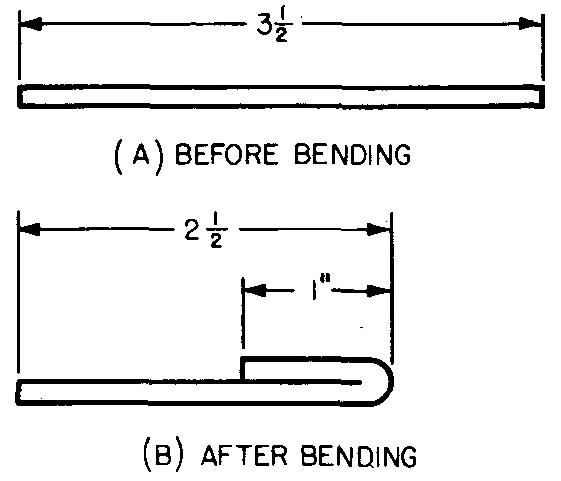
When an edge is folded or hemmed, as shown in Fig. 16-23, no bend allowance is necessary, since there is no important gain or loss in the size of the piece.
Fig. 16-23. A sheet-metal hem
Sheet-metal joints
It is important for the machine draftsman to know of some of the common methods used to fasten sheet-metal pieces together. Some companies prefer to specify on the drawing the type of joint desired. Other companies omit showing joints on the drawing, leaving the selection of the joints to the discretion of the sheet-metal worker.
Previously in this chapter we learned of the various methods which are used to fasten thick pieces of metal together by welding. Sheet-metal pieces are often joined by welding also, especially in cases where leak-proof conditions are required. Assembling parts by welding often proves to be the easiest and neatest method.
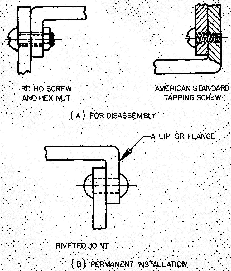
Some parts are fastened with rivets, or with screws and nuts, particularly in cases where parts must occasionally be disassembled. Here, projecting edges or flanges, called lips, are often made so that one piece may be fastened to another. Joints are usually made along the shortest edge or surface.
Figure 16-24 shows how pieces may be fastened by these methods.
Fig. 16-24. Sheet-metal joints—riveted and screwed
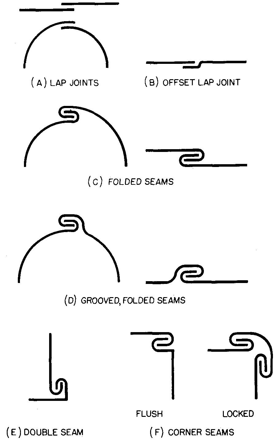
Other parts may be joined together by means of seams. Some seams are soldered to make them leak-proof. Figure 16-25 shows several types of seams.
Fig. 16-25. Sheet-metal seams
Removing sharp edges
Sheet-metal parts often have sharp and dangerous edges. When the machine draftsman prepares sheet-metal drawings, he must be constantly on the alert for any exposed edges of the part which may become a safety hazard.
Attention should be given to parts such as trays, pails and buckets, lockers, and metal chairs. Metal edges may be somewhat dulled by filing, but a more practical method is to fold or hem the edges, as shown in Fig. 16-23.
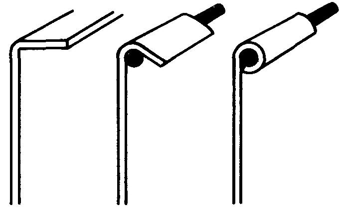
In this way the edge is stiffened and the part made more rigid. Another method, shown in Fig. 16-26, is to design a wire edge on the part. This method involves enclosing a strip of wire in the edge.
Fig. 16-26. A wire edge
Sheet-metal drawing practices
In so far as the machine draftsman is concerned, standards for sheet-metal drawings include all of the usual drawing rules which are required for any other kind of shop drawing. There are, however, two basic differences.
First, because of the thin metal walls on parts, it is usual to show the thickness of the wall by drawing only one line. (Most draftsmen show one line to represent thickness for metals of #11 US Std gage (0.125 inch) or less.)
Secondly, some parts require a special development drawing. This drawing is usually made full scale if possible. It shows the pattern, or outline shape, of the individual piece or pieces before bending.
A sheet-metal development drawing may be compared to a common cardboard box which has been opened at the joints and flattened out.
In this case, the boxmaker must carefully plan his pattern so the final box may be bent and joined to the desired final size and shape. Sheet-metal parts which are bent to shape must also be carefully planned before bending.
We have learned thus far of certain drafting practices which may be slightly different, depending upon the particular company. Sheet-metal drafting is no exception.
Depending upon the kind of product, available shop equipment, methods of assembly, and other important requirements, many companies establish slightly different requirements for the preparation of sheet-metal drawings.
In making each piece of a sheet-metal part, the shopman begins by accurately laying out the outline of each piece on a flat sheet of metal. In so doing, he uses principally the same kind of tools as the draftsman uses. Instead of using a pencil to draw lines on the metal sheet which would be hard to see, the shopman scratches or scribes lines with a steel tool called a scriber.
The outline of the piece is generally scribed on the inside face of the metal sheet so that all marks will be concealed after the piece is bent to shape. The piece is then cut, bent to shape, assembled with and fastened to all the other pieces to form the finished part.
It must be noted that the sheet-metal worker makes the development of the pieces directly on the metal sheet while using the dimensions given on the drawing.
Since his development must be accurate, the shopman is not permitted to trace or to punch points of intersecting lines directly from the drawing.
The drawing, though drawn to an accurate scale, may change slightly in size in the printing process. This size change is caused by shrinking or stretching of the print. Thus the print is not considered accurate enough to use as a pattern or template for the development.
Since we know the sheet-metal worker must make his own development, why, then, are developments frequently shown on sheet-metal drawings?
The answer lies in further examining the requirements of industry.
Some companies require their draftsmen to prepare only the usual views of a part and thus entirely omit making a development drawing. Other companies require development drawings only for parts which may be especially complex.
A development drawing would not be prepared for simple square or rectangular ducts used in heating and ventilating, for example.
Parts such as these can be made from the regular views of the part on the drawing. Work of this kind is classified as brake work, which means the parts are formed to shape by the press brake.
Finally, some companies require the preparation of development drawings of all sheet-metal parts, regardless of their shape.
Features of pieces such as holes and cuts are often more easily understood on a development rather than on the regular views.
In any case, the beginning draftsman should become familiar with as many as possible of the drawing requirements pertaining to the preparation of sheet-metal drawings.
The important thing to remember is that a development drawing serves principally as a guide to the shopman and shows him the size and shape of each piece before bending. Figure 16-27 shows a commercial drawing of a four-piece 90° pipe elbow.
Fig. 16-27. A four-piece 90° elbow
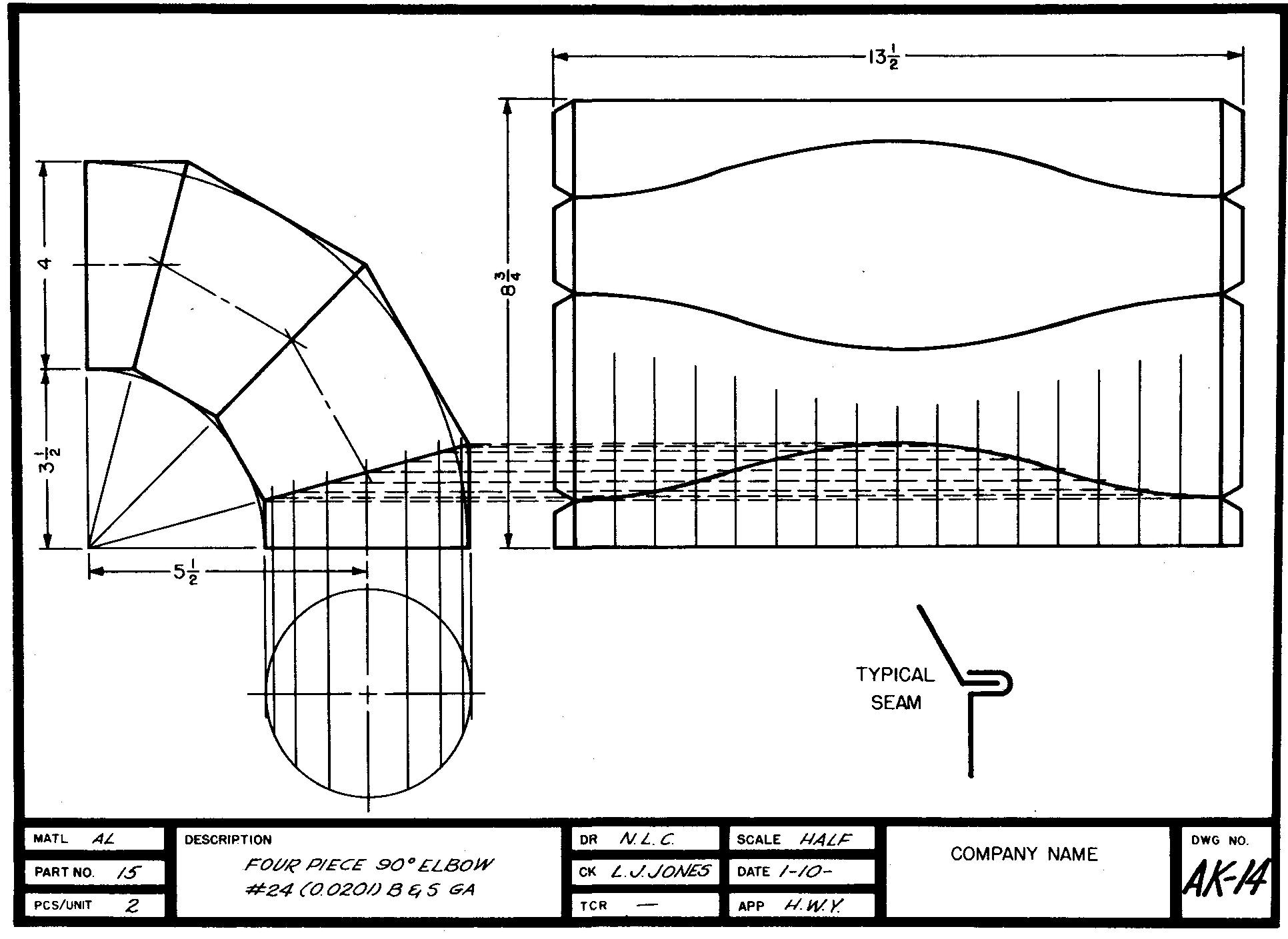
The usual views of the elbow are drawn and, in addition, a development drawing is also provided. Notice particularly how each of the four pieces is planned so it may be cut from one sheet with no waste of material.
On sheet-metal drawings, many companies add a parts list which includes items similar to those found on parts lists for welding drawings. The developed length of parts is usually given together with a listing of specifications and quantities of required fasteners (rivets, screws, nuts, washers, and so on).
The following examples will acquaint the student with methods of preparing drawings of some of the more common shapes of sheet-metal objects. Since it is impossible to give examples of all of the possible shapes which might be developed, a sampling is given showing only typical objects.
It should be noted that practically all sheet-metal objects are composed of combinations of these basic shapes, shown in Figs. 16-28 through 16-35.
Fig. 16-28. developing a prism : the principle
1. Draw the top and front views of the part.
2. Start the development at point 4, which has been conveniently located as shown. Draw the stretchout line (equal in length to the perimeter). Disregard bend allowance.
3. Step off the true length distances as shown.
4. Project heights from the front view.
5. Add bottom and top pieces if required.
6. Draw edges for joints
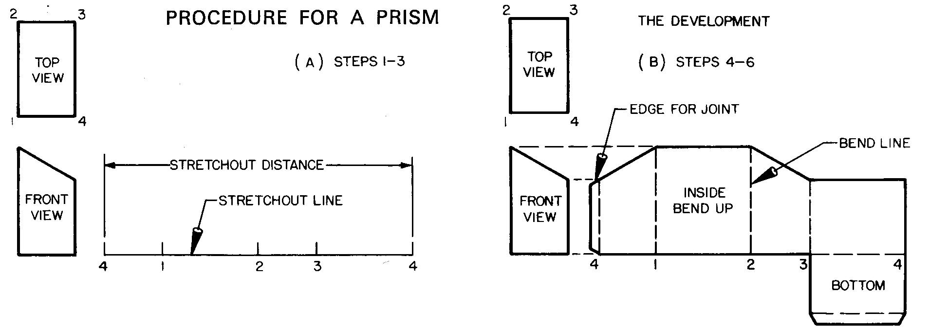
Fig.16-29. Developing a prism : the application
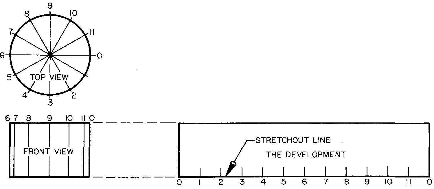
Fig. 16-30. Developing a cylinder: the principle
PROCEDURE FOR A CYLINDER
1. Draw the top and front views.
2. Divide the top view into any number of equally spaced parts.
3. Start the development at point 0, which has been conveniently located as shown. Lay off the corresponding divisions on the stretchout line. The exact length of the stretchout line may be found by using the formula C = πD.
4. Project the height of the development from the front view.
PROCEDURE FOR A TRUNCATED CYLINDER
1. See steps 1, 2, and 3 above.
2. Project the divisions from the top view to the front view. Draw the elements.
3. Extend element heights to intersect with the corresponding element set off on the development.
4. Connect points with a smooth curve.
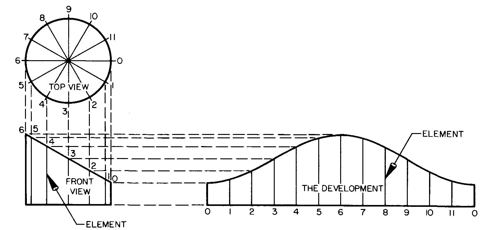
Fig. 16-31. Developing a cylinder: the application

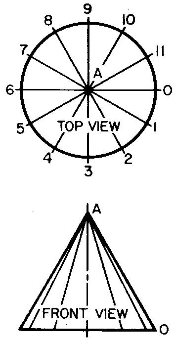
Fig. 16-32. Developing a cone: the principle
PROCEDURE FOR A CONE
1. Draw the top and front views.
2. Divide the top view into any number of equally spaced parts.
3. Starting at point A (at any convenient position on the development), with a radius AO taken from the front view, swing an arc of any convenient length.
4. Draw line AO at any convenient position. Starting at point 0, lay off the true length distances, 0-1, 1-2, 2-3, and so on, on the arc.
PROCEDURE FOR A FRUSTRUM OF A CONE
1. See steps 1, 2, 3, and 4 above.
2. Project the divisions from the top view to the front view. Draw the elements to intersect at vertex A.
3. Front view points a, b, c, d, e, f, and g (projected from the top view), are next projected horizontally to the right to intersect with element AO. Distances Ag, Af, and so on, are true lengths of these elements.
4. Transfer these distances to the corresponding element on the development.
5. Connect points a-b, b-c, c-d, and so on with a smooth curve.

Fig. 16-33. Developing a cone : the application
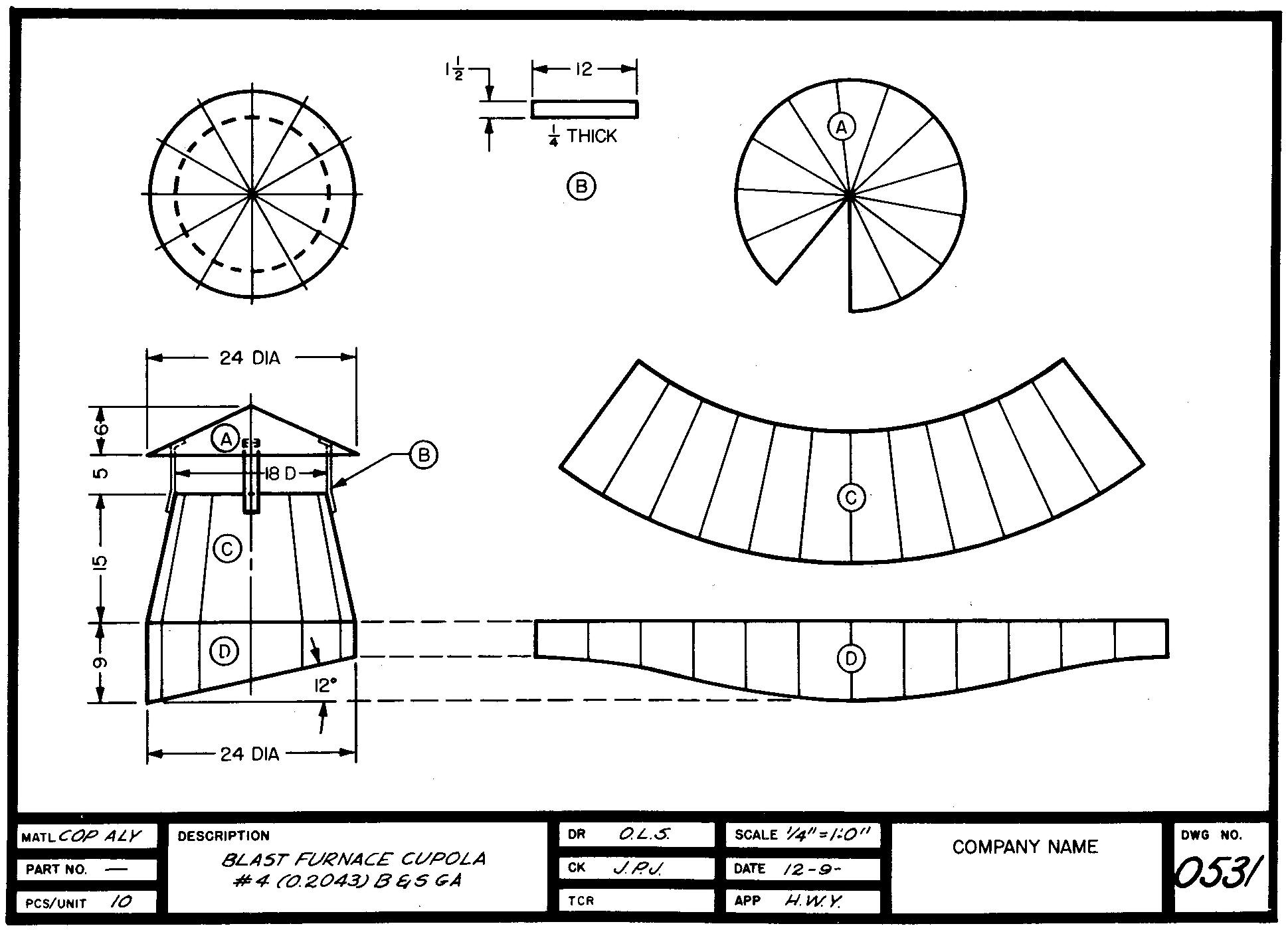
Fig. 16-34. Developing a transition piece : the principle
PROCEDURE FOR A TRANSITION PIECE
1. Draw the top and front views of the transition piece.
2. Divide the circle in the top view into any number of equally spaced parts. Draw the elements from these divisions to the corners.
3. Since the elements in the top view are foreshortened, they are not true length. Revolve the elements as shown and project to the front view. The elements are now true length. Elements drawn from base corners to points 0 and 6, 1 and 5, and 2 and 4 are respectively equal.
4. The center line ad in the top view divides the transition piece into two equal halves. Start the development at point a which has been conveniently located as shown. Lay out the development using the true length element lines as shown and true length distances a-b, b-c, c-d and 0-1, 1-2, 2-3, and so on.
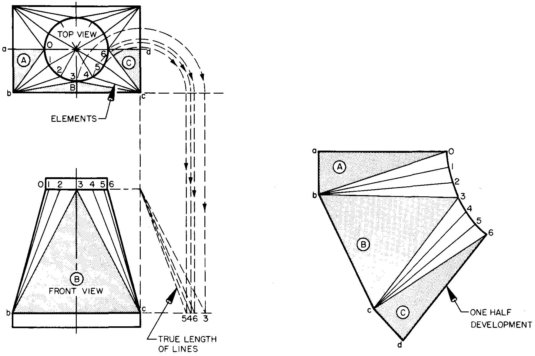
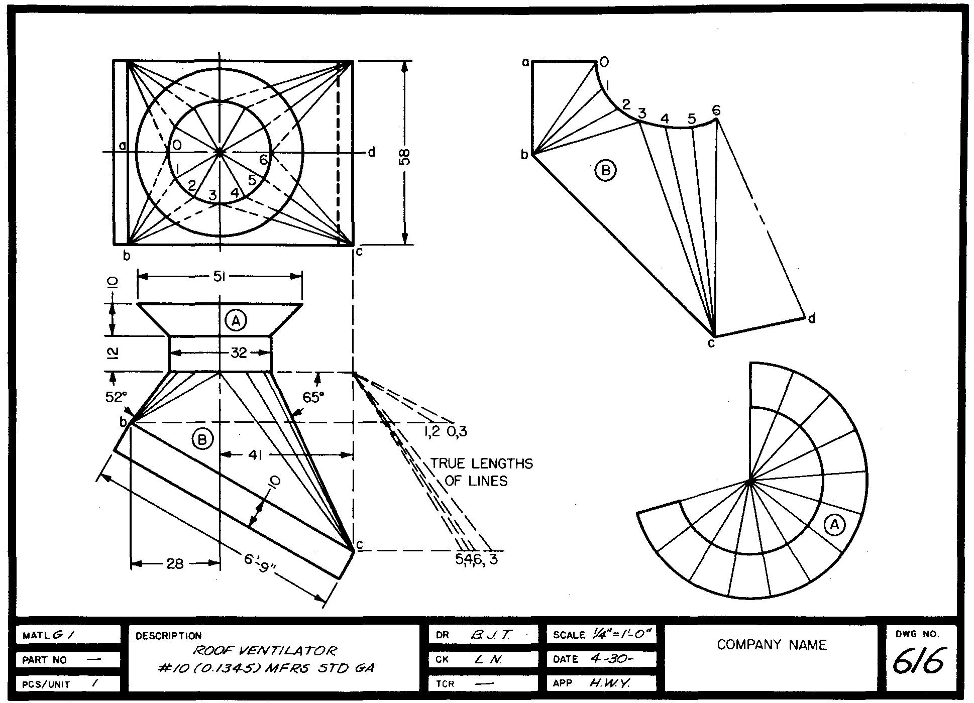
Fig. 16-35. Developing a transition piece: the application
Review questions
1. What is meant by fabrication!
2. In what way is welding, by any welding process, distinguished from other common methods of fastening metal pieces together?
3. Briefly describe the process of fusion welding.
4. Briefly describe the process of pressure welding.
5. Define a welded joint.
6. What is the purpose of a welding symbol? Is the symbol drawn mechanically or freehand?
7. Sheet metals are thin metals. Give the limits of thickness for sheet metals.
8. What are some of the chief advantages of sheet-metal parts?
9. List some common materials used in sheet-metal work.
10. Explain what is meant by a sheetanetal gage number.
11. How does the thickness of sheet metals change as the gage number gets larger?
12. What is the name of the tool which may be used to measure sheet-metal and wire sizes?
13. What is meant by bend allowance?
14. How would a sheet-metal part which requires a 90° bend be changed in measurement to allow for the gain in size due to bending?
15. Sheet-metal parts are usually joined along which edge, or surface?
16. What is frequently done to a seam to make it leakproof?
17. By what two ways may a sheet-metal edge be made more rigid?
18. Describe a development drawing.
19. Why is it considered unnecessary for the draftsman to prepare a development drawing of a simple square or rectangular duct?
20. Explain the term brake work. Prepare welding symbols for each set of conditions:
21. Fusion weld; fillet on both sides.
22. Fusion weld; bead on other side.
23. Pressure weld; projection, spaced every 10 inches.
24. Pressure weld; spot, spaced every 5 inches.
25. Fusion weld; V-groove both sides, machine flush.
26. Fusion weld; fillet weld all around, machine to concave shape.
27. Pressure weld; spot, 25 required, grind flush.
28. Pressure weld; seam, chip finish to convex shape.
29. Fusion weld; bead on arrow (or near) side, chip finish, field weld.
30. Fusion weld; plug, both sides, 1/4 diameter root opening, 30° angle.
31. Fusion weld; V-groove on arrow (or near) side, 6 inches long, machine flush.
32. The top view of Fig. 16-19 illustrates three different types of welding symbols. Copy each symbol and explain what each describes. Note: The fractions 1/8, 3/16, and 1/4 refer to the size of the required welds.

![]()