
Forming parts by machining
Introduction
The study of forming parts by machining refers to the study of the processes of making a part to the required size and shape by cutting it from raw stock.
Examples of parts made in this way are shown in Fig. 13-1. Some of the shapes of stock available for machining parts are shown in Fig. 13-2.
Fig. 13-1. Parts made from stock

Fig. 13-2. Shapes of standard stock

Machines which are used to cut metal parts are called machine tools.
The work done by machine tools can be compared to the work the carpenter does with hand tools. The carpenter saws wood with a handsaw, drills holes with a brace and bit, and smoothes the surfaces with a hand plane. He may, of course, use machines to do the same things.
The machinist, working in metals, cuts, drills, planes, grinds, or shapes parts with power driven machines. Cutting, drilling, planning, and so on are called machine operations.
There are many different kinds of machines for various metalworking operations.
Each is especially designed to do a certain kind of work. In fact, there are well over 400 types of machine tools and a number of sizes of tools of each type. For each size and type there are many special work-holding and tool-holding devices called attachments.
In addition, there are many special machine tools which have been built to perform not one, but a whole succession of operations, once the part to be worked on has been loaded into place.
The operator on such a machine literally does not touch the work from the beginning to the end of a series of operations. These machines are called transfer machines.
The outstanding feature of machine tools of today is the great precision with which they can remove or form metal (see Table 5).
Dimensions on a part can be measured accurately on a comparative basis to a millionth of an inch. This is about 1/3000 of the thickness of a human hair!
The variety and number of combinations of machine tools in use today are almost unlimited. Some are so small they may be mounted on a workbench.
Others are as large as a three-story house. They range in cost from less than a hundred dollars to hundreds of thousands of dollars. Some machine tools weigh several hundred tons and require a large area for their operation.
The five basic operations
Large or small, machine tools can be divided into five general groups, called the five basic operations of machining metal. These are drilling and boring, turning, milling, planing, and grinding. Any of these may be combined for unusual situations.
There are, for example, a number of machines which combine two or more basic operations, such as a boring, drilling, and milling machine.
American technicians particularly excel in the design and construction of these variations of combinations, which are limited only by the ingenuity of machine designers and tool engineers.
Drilling and boring
These basic processes are described in section 12. Basic machining operations Part 1 for a description of drilling and for boring.
Turning
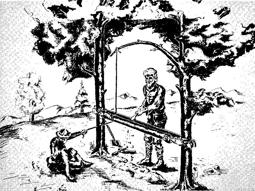
The lathe, as the turning machine is commonly called, is the father of the entire machine tool family. Its principle has been known since the dawn of civilization. Its probable origin was the potter's wheel, a machine used to make pottery. The tree lathe, shown in Fig. 13-3, was one of the earliest types of turning lathes.
A rope, attached to a flexible tree branch overhead, was passed around the work to revolve it. Later a strip of wood, or lath, was used to support the rope, and this is probably why the turning machine came to be known as a lathe.
Fig. 13-3. A tree lathe
One of the earliest screw
cutting lathes was built in France about 1740. It was operated by turning a hand
crank.
In 1797, Henry Maudslay in England developed a small lathe which could
be used to cut both fine and coarse screw threads. This was an improvement over
earlier models.
American lathes were first produced about 1800.
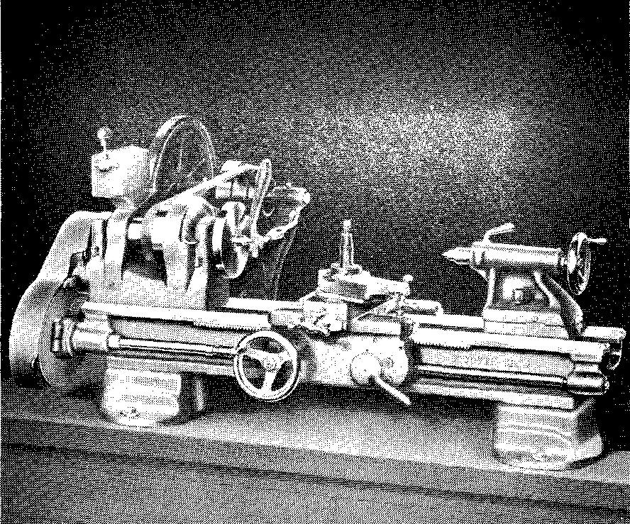
The modern standard bench lathe, shown in Fig. 13-4, was developed as a result of continual changes and improvements to the lathes of the early 1800s.
Fig. 13-4. A modern standard bench lathe
No other machine tool has played such an important part in the development of the industrial history of the United States. Without the lathe, it would have been impossible to produce steamboats, locomotives, early rifles and cannons, and all kinds of machinery.
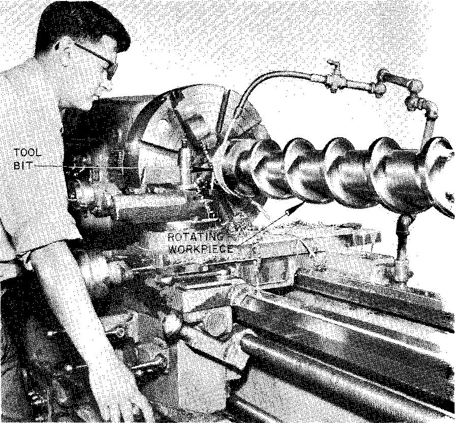
Turning consists of machining a piece of rotating metal by pressing a hardened cutting tool against it, as shown in Fig. 13-5.
Fig. 13-5. Machining a part on a lathe
There are many special attachments which permit the lathe to be used for other operations such as drilling, boring, thread cutting, milling, and grinding. The lathe is the only machine tool which is capable of reproducing itself without the use of other machine tools.
The turret lathe, Fig. 13-6, is equipped with a six-sided tool holder called a turret, to which a number of different cutting tools may be attached.
Fig. 13-6. A turret lathe
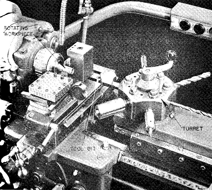
The turret, with the various cutting tools, makes it possible to do several different operations over and over again without resetting or changing the tools.
So that thousands of identical parts may be produced quickly and inexpensively, an automatic multiple spindle bar machine, Fig. 13-7, is used.
Fig. 13-7. An automatic multiple spindle bar machine (screw machine)
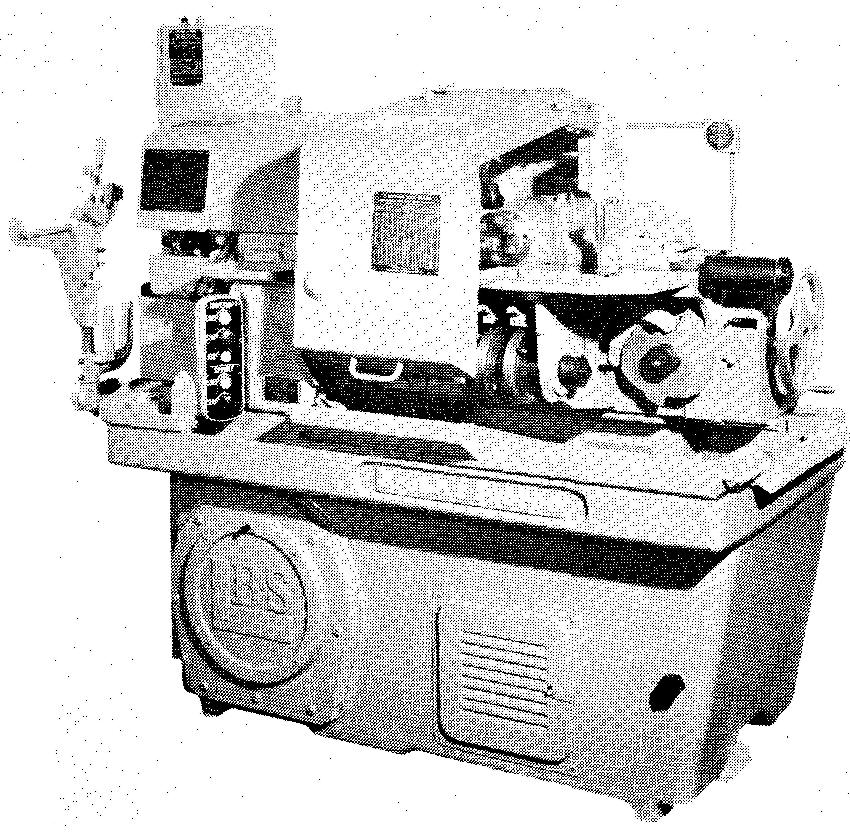
This machine performs six different operations at one time on six parts. Once set up and put into operation, it relieves the operator of all but two duties: to feed in long metal bars and to take away finished parts.
Milling
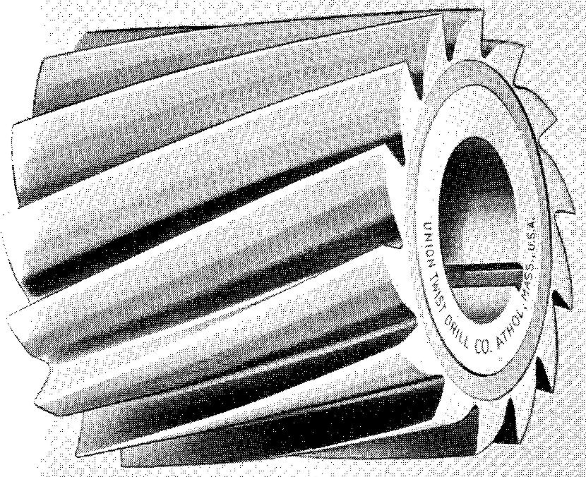
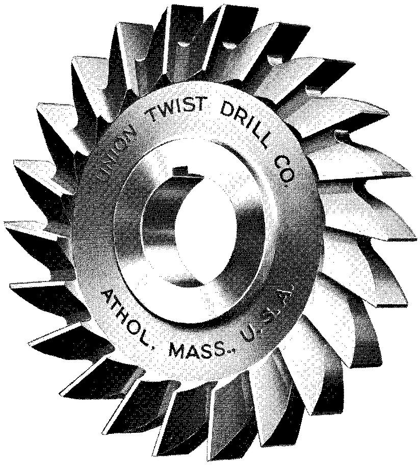
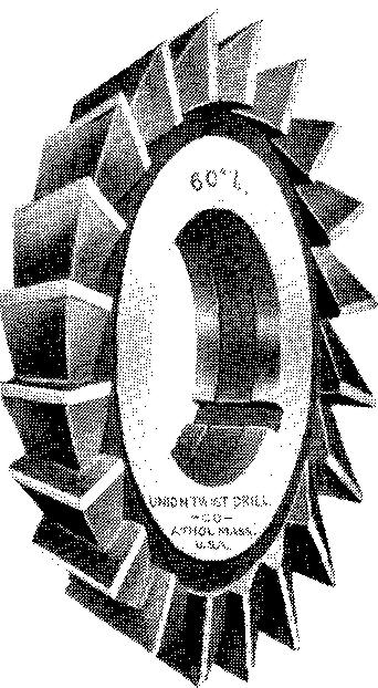
When metal is removed from a piece of stock by bringing it into contact with a rotating cutter tool having many cutting edges, the stock is being processed by milling.
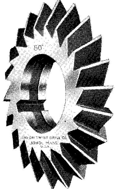
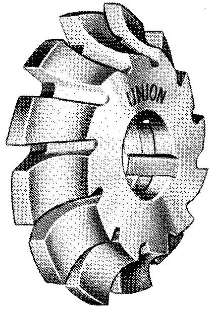
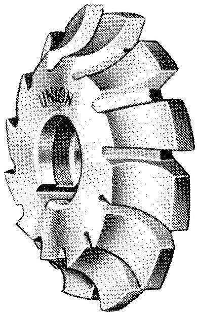
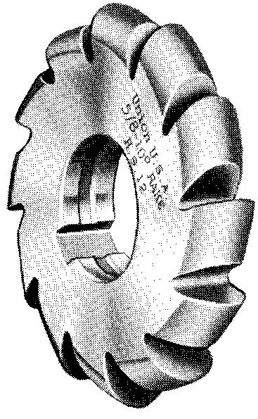
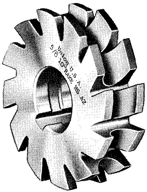
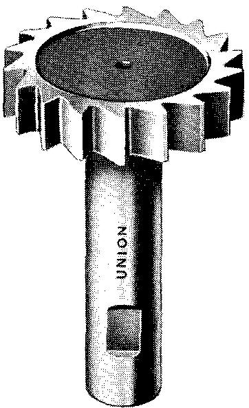
A narrow milling cutter resembles the woodworking circular saw blade familiar to most people. Other cutters have spiral edges which give the cutter the appearance of a huge screw. Figure 13-8 shows various types of cutters commonly used on a milling machine.
Fig. 13-8. Common types of milling cutters
| (A) solid plain mill | (B) side mill |
 |
 |
| (C) single angle cutter | (D) double angle cutter |
 |
 |
| (E) corner rounding form relieved cutter | (F) corner rounding form relieved |
 |
 |
| (G) convex form relieved cutter | (H) concave form relieved cutter cutter |
 |
 |
| (I) solid T slot cutter | (J) Woodruff keyseat cutter |
 |
 |
| (K) taper shank end mill | |
 |
A milling machine such as
the one shown in Fig. 13-9 is capable of producing a wide variety of cuts.
Fig. 13-9. A milling machine
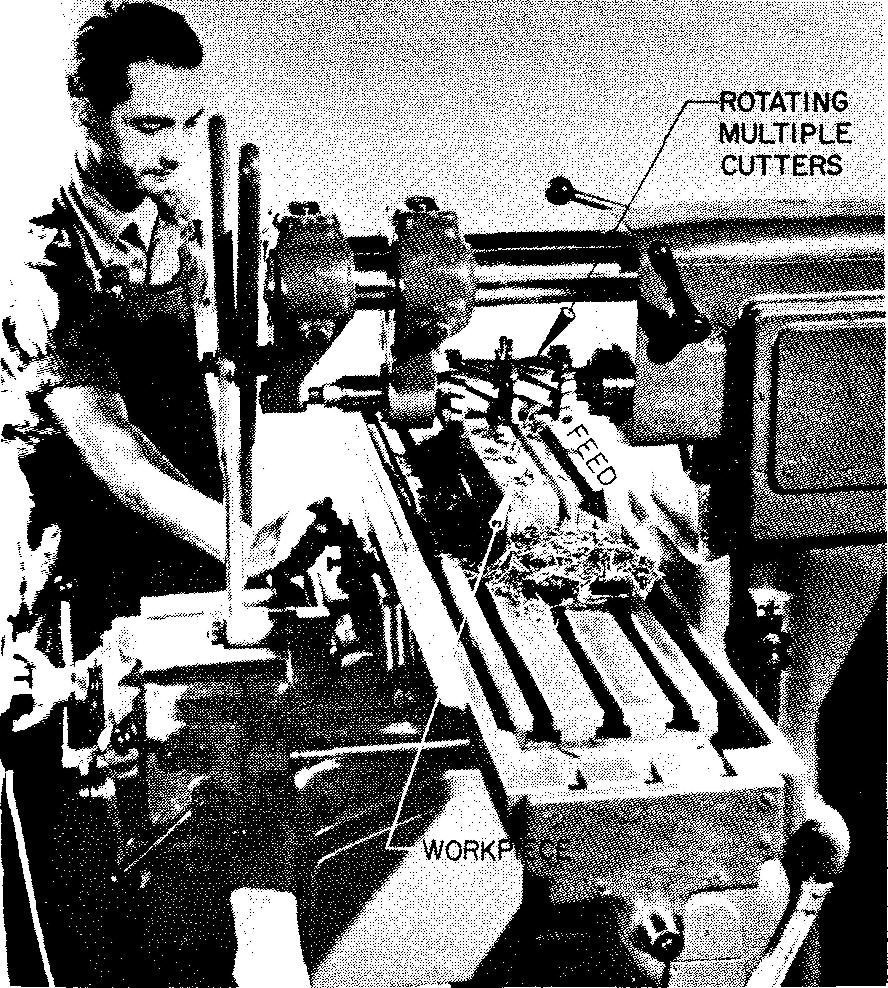
It is possible to produce many combinations of flat and curved surfaces; to mill internal and external cylindrical or round surfaces; to cut gear teeth, threads, and slots; and to drill, ream, and bore holes. Milling machines are widely used in manufacturing. They are capable of working to very precise dimensions.
Planing
Planing (or shaping) metal with a machine tool is a process somewhat similar to planing wood with a carpenter's hand plane; the main difference being that the tool remains rigidly in place while the part or parts to be planed are moved back and forth beneath it.
A planer is generally a large piece of equipment. In fact, some planers can machine surfaces measuring from 15 to 20 feet wide by twice as long. Figure 13-10 shows a planer set up to plane a horizontal surface.
Fig. 13-10. A planer
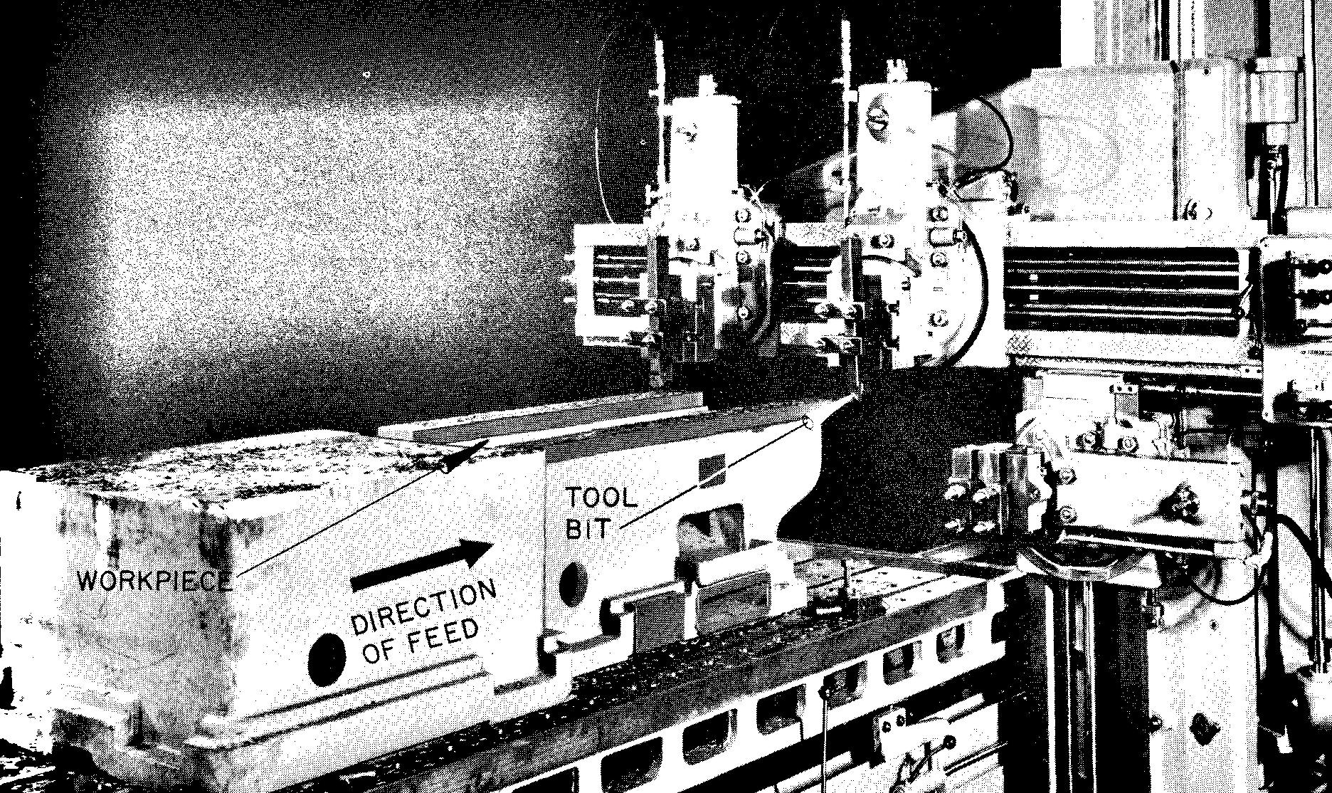
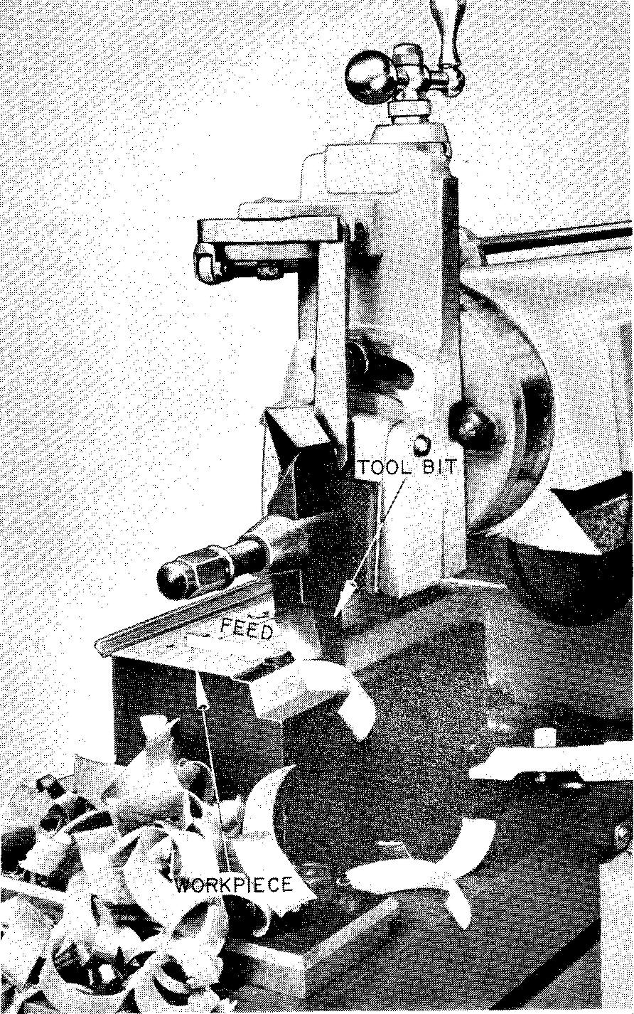
A shaper, Fig. 13-11, works in a manner just the opposite from a planer. Shaping consists of machining work with a cutting tool which travels back and forth against the work-piece which is held rigidly in place.
Fig. 13-11. A shaper
Other machine tools included in the planing machine group are called slotters and broaches. The slotter, known also as a vertical shaper, is used largely for cutting gear teeth, keyways, slots, and so on.
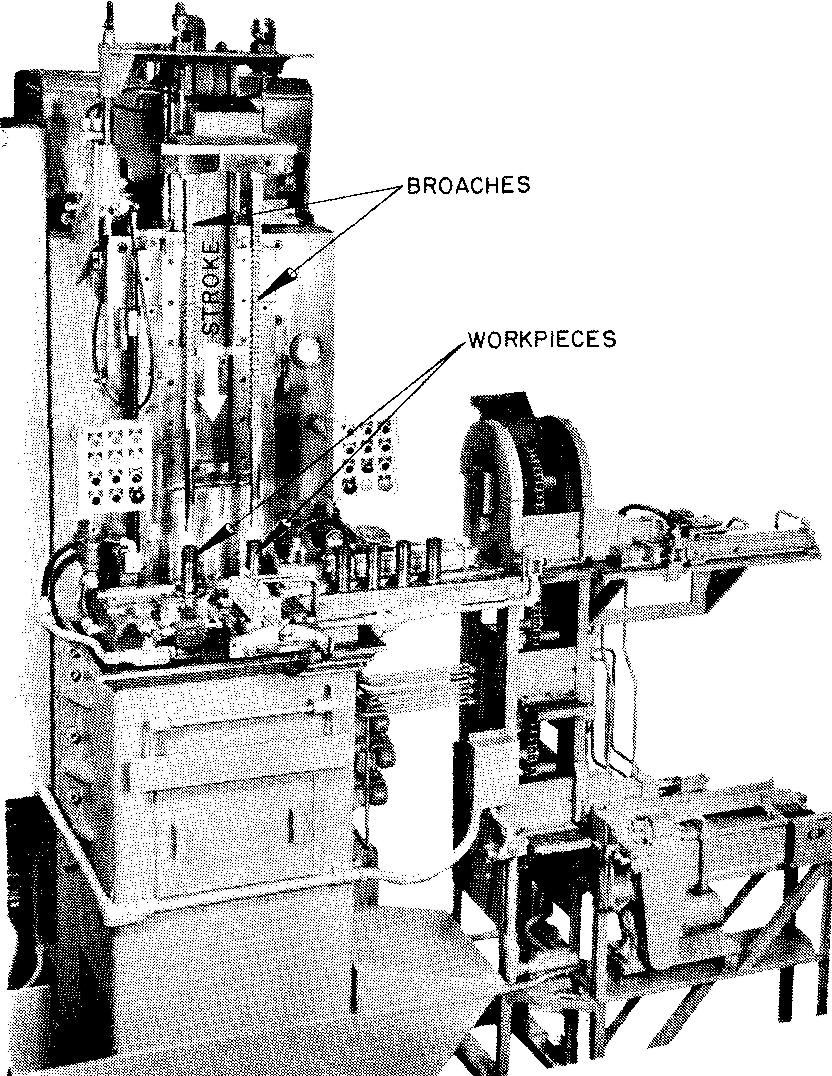
Broaching machines, shown in Fig. 13-12, closely resemble a planer in the way they operate.
Fig. 13-12. Broaching (A) a broaching machine
(B) Holes of practically any shape can be broached
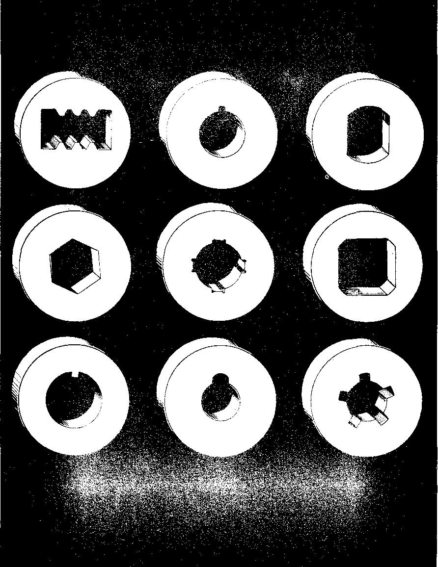
In general, parts which can be formed by milling, drilling, shaping, and so on can also be broached. Broaching operations are often specified when the quantity of parts to be machined is sufficiently large to offset the use of special equipment. The broach has many cutting teeth which increase in size from the starting end to the rear support end.
Since the cutting edges on each tooth are progressively higher, each successive tooth removes an additional amount of stock. The broach is mechanically pulled or pushed through or past the surface to be finished. It is frequently used internally; for example, to finish a previously formed round, square, or irregularly shaped hole.
Planers and shapers can produce horizontal, vertical, or angular flat and irregular surfaces and slots. They are also used to form to size various shapes of internal holes. A vertical shaper is often called a slotting machine.
Grinding
Grinding is one of the most interesting operations in all of metal working. Before the development of the modern grinding wheel, most metalworking was limited to what could be done with metal tools and very crude grinding equipment. Today any kind of finish can be obtained on any kind of material.
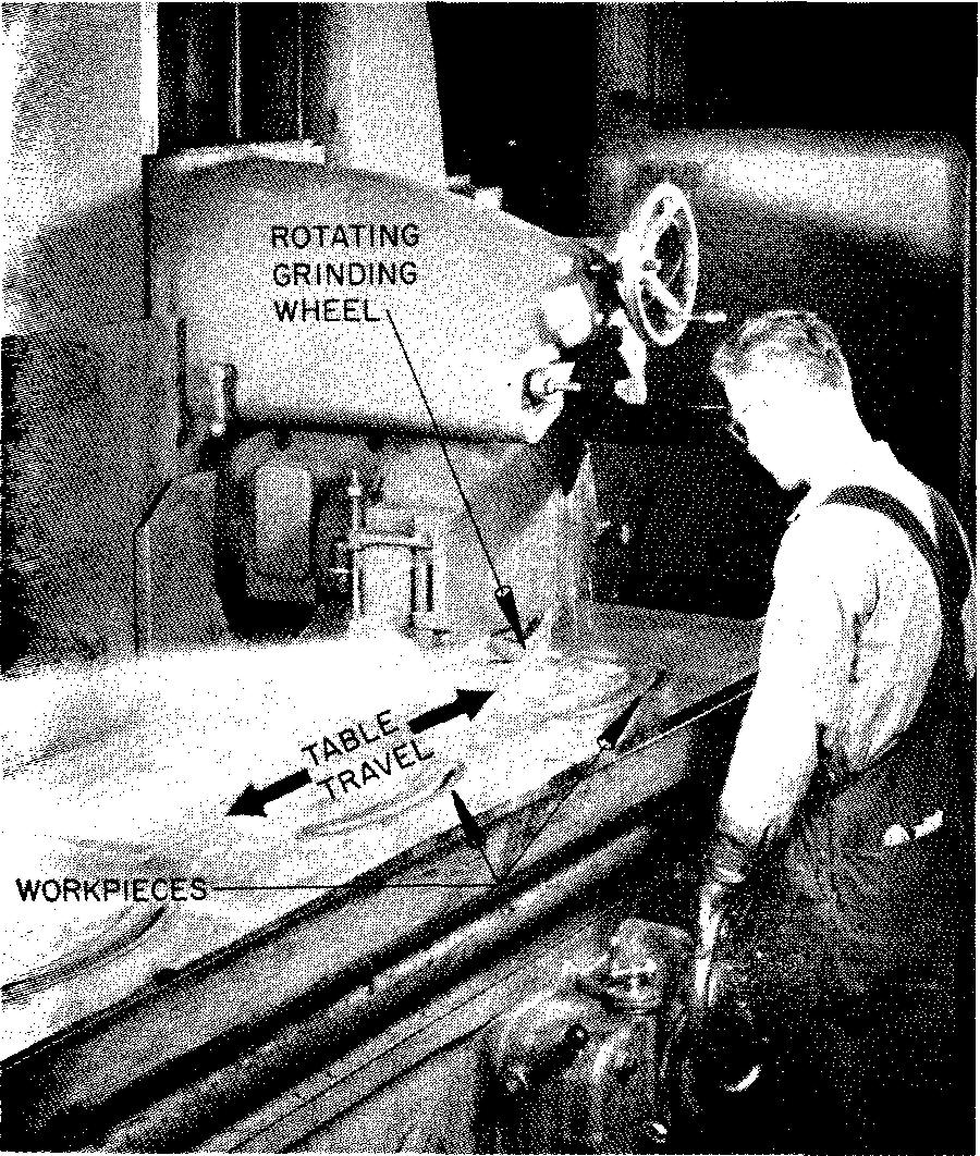
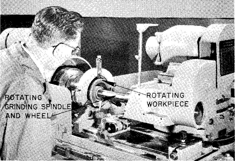
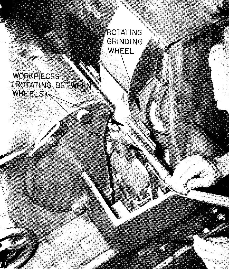
In the machine operation of grinding, a workpiece is brought into contact with a rotating abrasive wheel. It is by grinding that a part is finished to a very precise size.
When metal parts are heat-treated (or hardened), they often warp or twist slightly. Grinding corrects any distortion that may result. Grinding is a method used to smooth surfaces, to sharpen cutting edges of tools, and to cut off stock to size. External cylindrical surfaces, holes, flat surfaces, gear teeth, and precision threads may be formed by grinding.
Grinding wheels are made in a great many different shapes, sizes, and degrees of roughness. Some of the more common types of wheels are shown in Fig. 13-13.
Fig. 13-13. Various shapes of grinding wheels
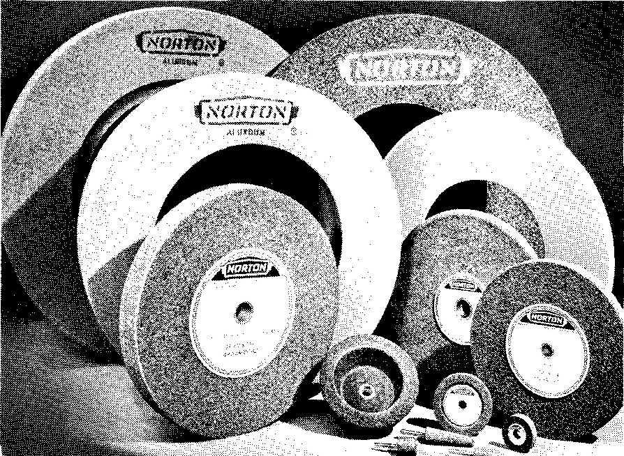
They are used on various types of grinding machines and for many different kinds of work.
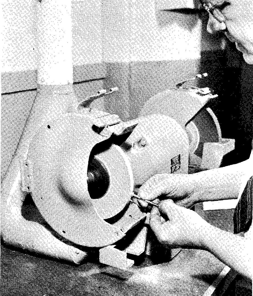
There are many kinds of machines used for grinding metal parts. Perhaps the most common is the bench grinder, shown in Fig. 13-14A, which is found in most service stations, small shops, and so on.
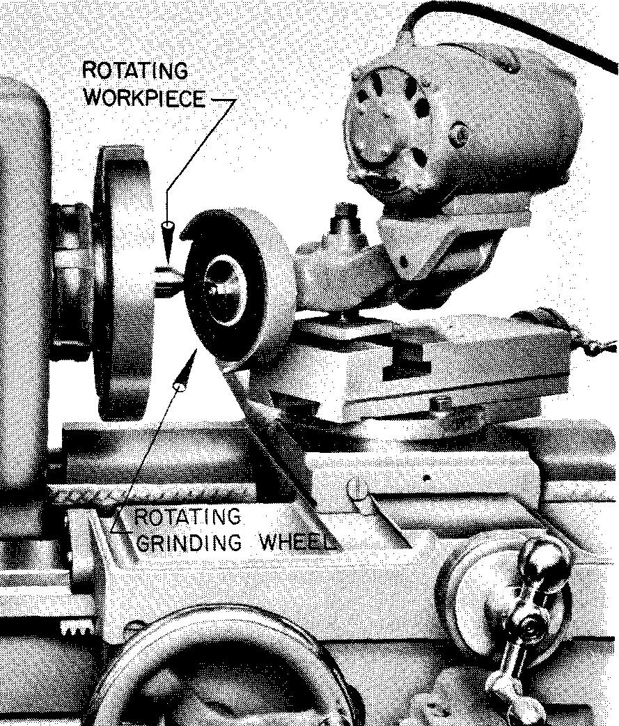
This machine is generally used to grind small parts held by hand. The tool post grinder, Fig. 13-14B, is a small portable machine which may be attached to a lathe, a planer, or a shaper.
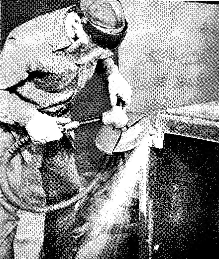
Flexible shaft grinders, Fig. 13-14C, are used for finishing dies and metal patterns, for smoothing the rough surfaces and edges of castings, and so on.
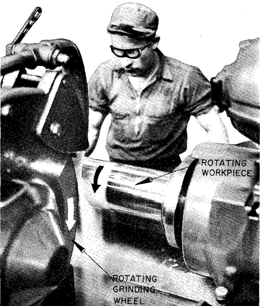
Grinding machines which grind round parts such as shafts and pistons are called cylindrical grinders, Fig. 13-14D. Surface grinders, Fig. 13-14E, are used for finishing flat
Fig. 13-14. Grinding machines
| (A) a bench grinder | (B) a tool post grinder |
 |
 |
| (C) a flexible shaft grinder | (D) a cylindrical grinder |
 |
 |
| (E) a surface grinder | (F) an internal grinder |
 |
 |
| (G) a centerless grinder | |
 |
Review questions (The answers are not given)
1. Define the terms machining and machine tools.
2. List the five basic operations of machining metal.
3. Describe the operation known as turning.
4. Describe the operation known as milling.
5. Describe the operation known as planing.
6. How do planing and shaping differ?
7. What is a slotter used for?
8. Under what conditions are broaches used?
9. Describe the operation known as grinding.
10. What types of grinding machines are used to grind outside surfaces of cylindrical parts?
11. What kind of grinding machine is used to grind flat surfaces of parts?
12. Name a grinding machine which could be used to sharpen a lathe tool bit.
Problems: forming parts by machining
Prepare detail drawings of the problems which are shown on the following pages. It will be necessary to study all of the information contained on the illustration and also the data which accompany each problem.
References have been provided for the important elements of each problem such as machining and manufacturing processes, drafting mathematics, heat treatment, hardness testing, tolerancing, information listed in the Appendix tables, and so on.
The references listed for each problem pertain only to material not found in section 2 through 7 and in section 13. All references should be carefully checked before starting the problem.
Space the required views carefully on the drawing sheet, allowing sufficient space around the views for dimensions and notes. For each problem prepare a detail title consisting of the part number, part name, pieces per unit, material, and the finish specifications, heat treatment, and hardness test number as required.
Important — In most cases, only the critical dimensions of each part have been given. Sizes of some of the less important features of parts have been intentionally omitted, leaving the selection of these sizes to the discretion of the student.
For drawing purposes, features of parts which appear to be located on center with corresponding edges may be assumed to be central. It is important for the student to give those dimensions which locate all of the features of the part, thus eliminating any possibility of guesswork if the drawings were to be actually used in the shop.
Do not copy the given dimensions. In many cases, the given dimensions would not be suitable for use on a two- or three-view detail drawing.
Problems in this section are all similar in that each part is machined from commercially available stock (rods, bars, or plates).
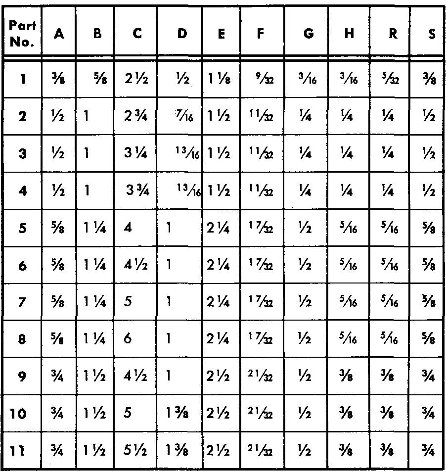
problem 13-1 clamp strap
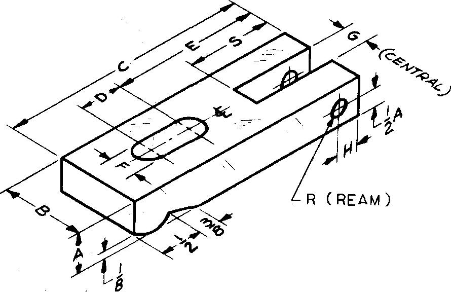
Sheet Size 8-1 /2 x 11 Drawing Scale Full
Material 1020 Steel Pieces per Unit 1
Heat Treatment Pack carburize, .008 inch thick Hardness Test and Number Rockwell 30N, 70-72 References Sees. section 9 (Pack Carburizing, hardness testing), section 12 Reaming, and slots and grooves (Figs. 12-51 and 12-52); Table 6 Blued finish.
Draw Parts 1 through 11 as directed.
problem 13-2 pipe hanger

Sheet Size 8-1/2x11 Drawing Scale Full
Material 1015 Steel Pieces per Unit 2
Final Part Size 1 /4 inch x 1 inch
References Sees. 10.17 (Example 1), 12.3 (Fig. 12-4); Tables 6 and 68 Bonderize finish.
Prepare a detail drawing of one pipe hanger only. Use standard welded wrought-iron pipe (3" nominal diameter).
Remove all sharp corners.
Specify the developed length (before bending) to the nearest 1 /8 inch.
Distance from center line of bolts to center line of pipe = 2-1 /2.
problem 13-3 swivel block
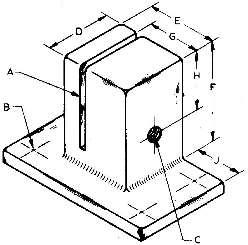
Sheet Size 8-1 /2 x 11
Drawing Scale Pieces per Unit 1
Twice Material Aluminum #43
Final Part Size Base Size — 1/8 x 1 x 1-11/16
References Sees. section 8 (Power Brushing; Fig. 8-25) and 12 (Fig. 12-42); Table 8 Power brush finish.
All radii 1 /32.
A — Slot, 1 /16 wide x 7/8 deep
B — 5/32 drill, 4 required, located 3/16 from each edge
C — #10-24 UNC-2 threads on one side only, tap drill extends entirely through block, central with D
D — 11/16
E — 3/4
F — 1-1/16
G — 9/16
H — 5/8
J — 1/2
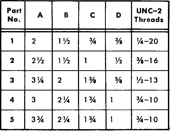
problem 13-4 eye bolt
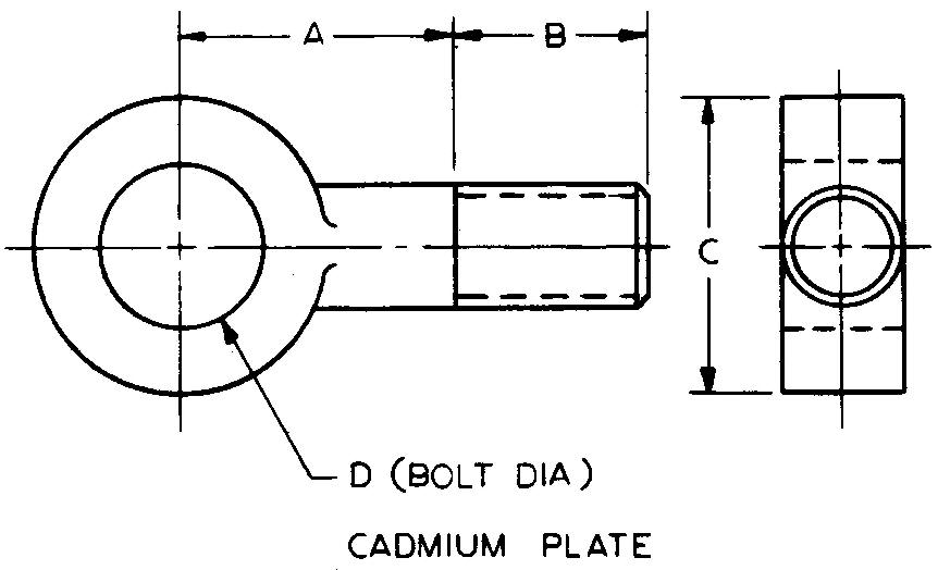
Sheet Size 8-1 /2 x 11
Drawing Scale Full
Material 1040 Steel Pieces per Unit 6
References Sees. section 12 (Fig. 12-4), (Fig. 12-35), and (Fig. 12-43); Table 6
Draw Parts 1 through 5 as directed. Use schematic thread symbol.
problem 13-5 plug gage
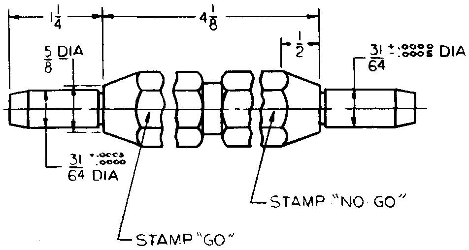
Sheet Size 8-1 /2 x 11 Drawing Scale Full
Material 6150 Steel Pieces per Unit 1
Final Part Size 7/8 octagonal stock x 6-5/8 long
Heat Treatment Quench and temper
Hardness Test and Number Shore 80-83.
References Sees. section 8 (Figs. 8-21 and 8-22), 9 (Quenching; Tempering), 9 (Shore Scleroscope), 10, 11, and 12 (Fig. 12-56).
Specify "Grind all over."
Center groove — 1/4 wide x 11/16 dia
Necks — 1/16 wide x 1 /64 deep
End chamfers — 1/4x10°
problem 13-6 vise jaw
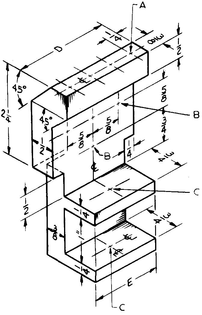
Sheet Size 8-1/2x11 Drawing Scale Full
Material Brass Pieces per Unit 2
Total Height 4"
References Sees. section 12 (Fig. 12-4), 12(Fig. 12-42), and 12 (Fig. 12-48); Table 8
Specify "Remove all sharp corners."
A — 1 /8 ream, 7/16 deep, 4 required, located 1 /2 center to center
B — 1 /4 ream, 4 required
C — 3/8-24 UNF-2 threads, 2 required
D —2 E-1-1/2
problem 13-7 coupling
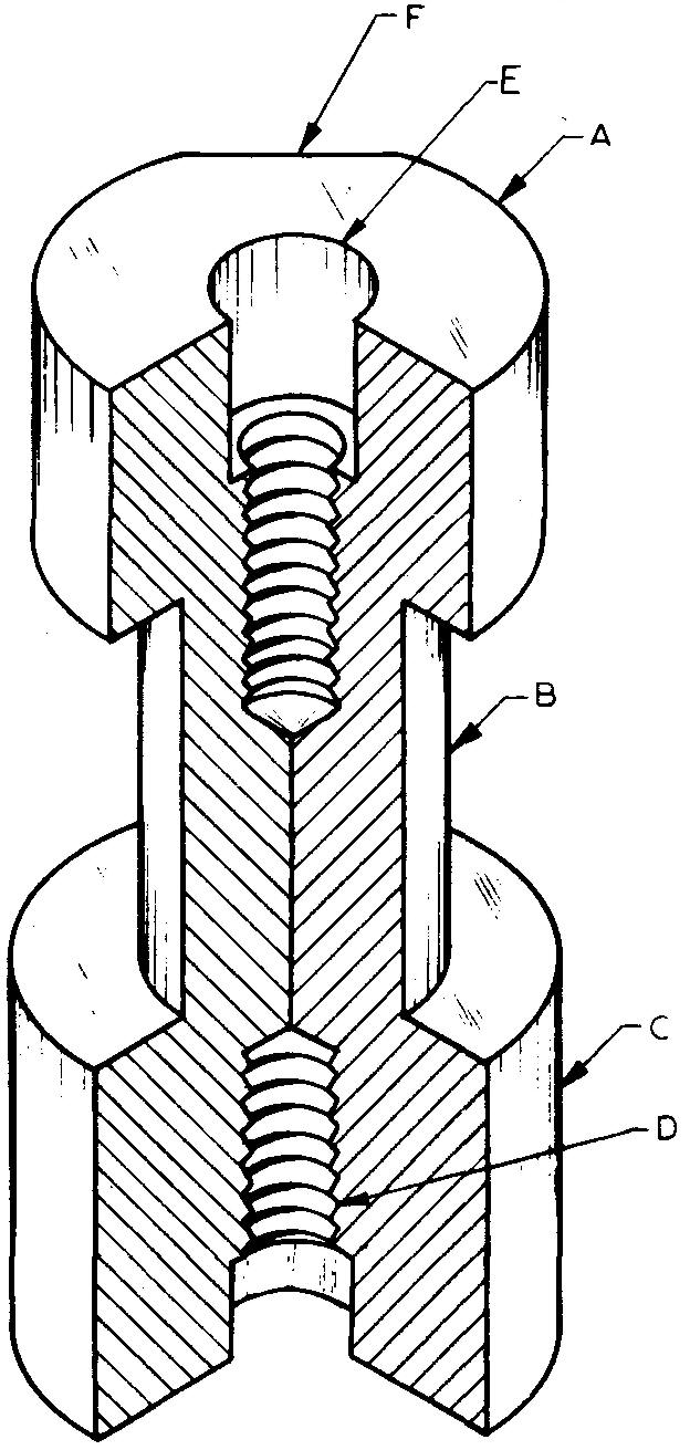
Sheet Size 8-1/2x11
Drawing Scale Twice Material Commercial Bronze Pieces per Unit 4
Final Part Size 3-1 /8 long
References Sees. section 8 (Polishing; Fig. 8-13), 12 and (Fig. 12-42); Table 8 Specify "Polish all outside surfaces."
A — 1-1/4 dia x 3/4 lg
B — 3/4 dia
C — 1-3/8 dia x 1-1/8 lg
D — 3/8-32 UNEF-3 threads, 3/4 deep, both ends
E — 31 /64 drill, 1 /2 deep, both ends
F — Flat, 3/8 wide on dias A and C
problem 13-8 link
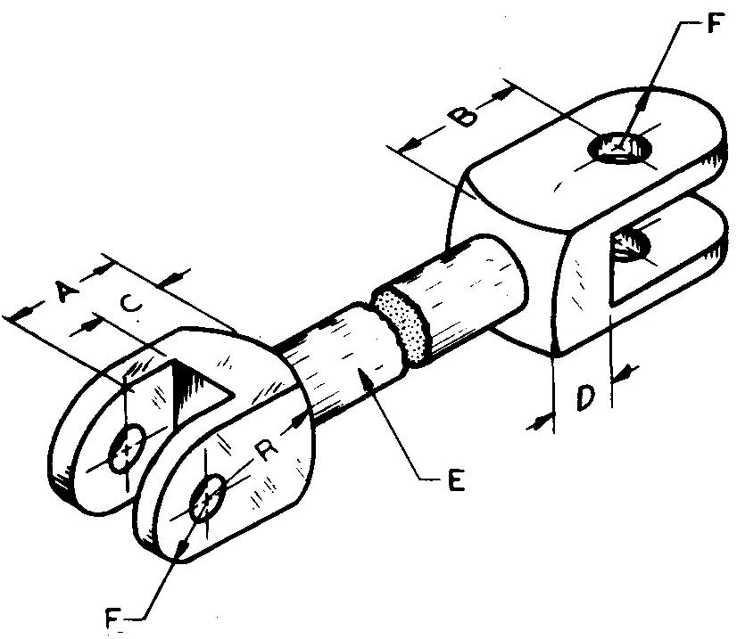
Sheet Size 8-1 /2 x 11 Drawing Scale Full
Material Brass Pieces per Unit 4
Final Part Size 7/8 square x 7-1 /4 lg
References Sees. 11.7 and 12.21 (Fig. 12-48)
Show a revolved section for E diameter.
Determine radius R by construction.
A — 7/8
B — 1"
C — 1/2
D — 9/16
E —5/8dia
F — 7/16R
Slots — 1 /2 wide, tolerance -.001, -.002
Small holes — 5/16 ream
Large holes — 7/16 ream
problem 13-9 knob
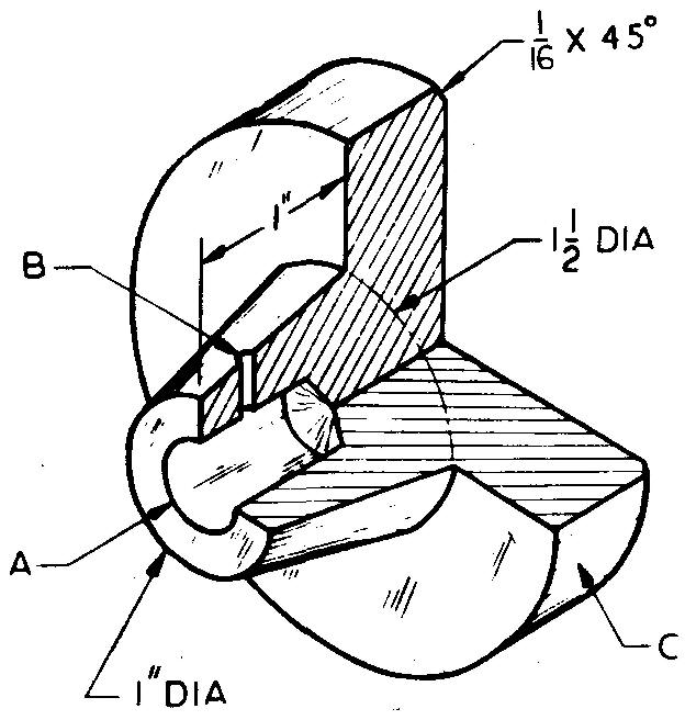
Sheet Size 8-1 /2 x 11 Drawing Scale Full
Material Aluminum #195 Pieces per Unit 2
Final Part Size 3" dia x 1 -11 /16 lg
References Sees. section 8. (Figs. 8-4 and 8-9), 12 (Fig. 12-4), 12 (Fig. 12-48), and 12.25 (Fig. 12-56);
Table 6 Annodize finish. Use a half-sectional view
A — 17/32 drill, 3/4 deep
B — 1 /8 ream, locate 11 /32 from near end
C — Medium knurl
problem 13-10 swivel clamp
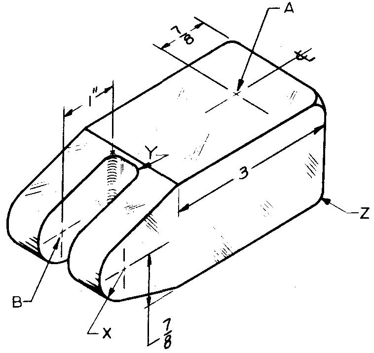
Sheet Size 8-1 /2 x 11 Drawing Scale Full
Material 1040 Steel
Pieces per Unit 5
Final Part Size 2 wide x 1 -3/4 thick
Heat Treatment Pack carburize, .012 thick
Hardness Test and Number 136° Diamond Pyramid 544
References Sees. 9 (Pack Carburizing), 9 (136° Diamond Pyramid), 11, 12 (Fig. 12-48), and (Figs. 12-51 and 12.52); Table 6 Black zinc finish.
A — 3/4 ream, 1 " deep
B — 7/16 ream, 2 required, locate 3-1 /4 from center line of A X-7/16R Y-.187 max R Z-1/4R
Slot — 5/8 wide, tolerance +.005
problem 13-11 tool post
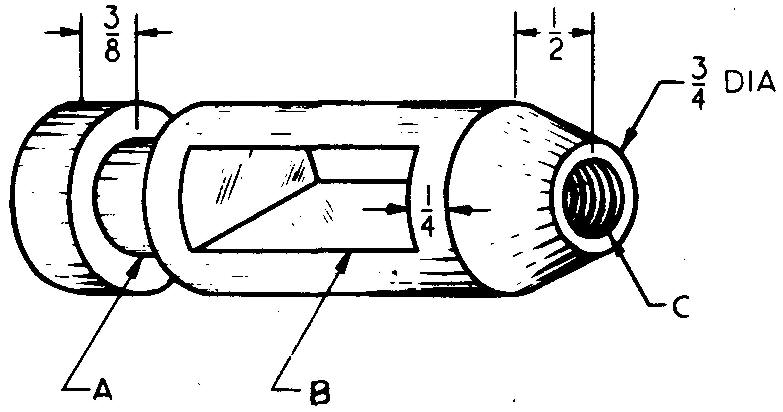
Sheet Size 8-1/2x11 Drawing Scale Twice
Material 3435 Steel Pieces per Unit 1
Final Part Size 1 -1 /4 dia x 3-3/8 lg
Heat Treatment Quench and temper
Hardness Test and Number Rockwell C 40-44
References Sees. 9 (Quenching; Tempering) and (Rockwell Hardness Test); Tables 6 and 8 Blued finish.
A - Neck, 1 /2 wide x 11 /16 dia
B - Slot, 11/16widex1-1/2lg
C - 1 /2-13 UNC-2 threads to slot
problem 13-12 pawl
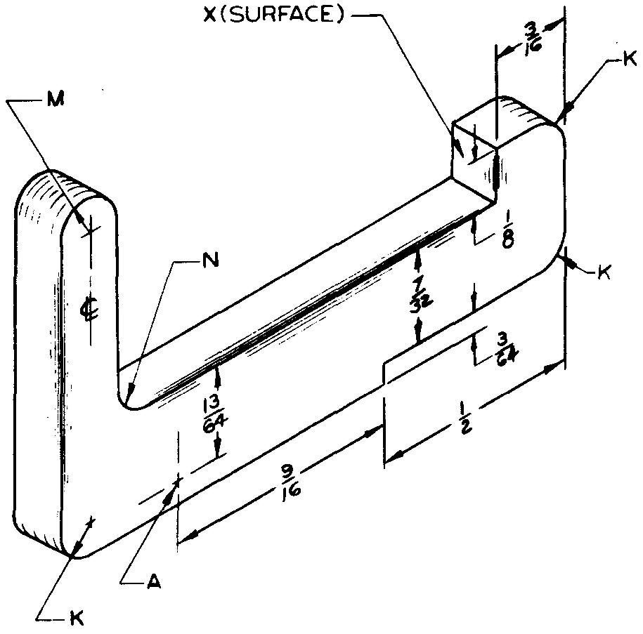
Sheet Size 8-1 /2 x 11 Drawing Scale Twice
Material 3115 Steel Pieces per Unit 1
Final Part Size 1 /8 thick x 7/8 wide x 1-3/8 lg
Heat Treatment Quench and temper
Hardness Test and Number Brinell (3000 KG) 285-293
References Sees. 8 (Figs. 8-21 and 8-22), 9 (Quenching, Tempering), (Brinell Hardness Test), 11, and 12 (Fig. 12-4); Table 6 Parco-Lubrite finish.
Tolerance on thickness + .002 Grind sides and surface X.
A-1/16 drill
M-1/16 R
K-1/8R
N-3/32 R
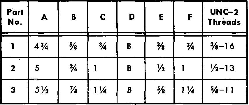
problem 13-13 swing bolt
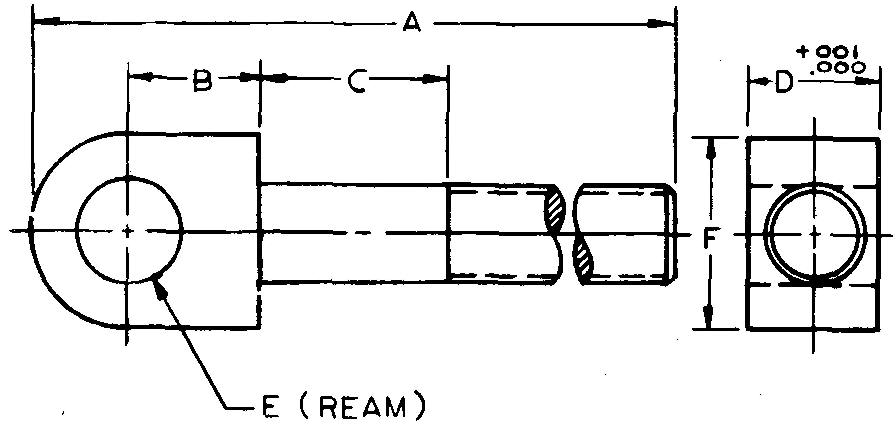
Sheet Size 8-1/2x11 Drawing Scale Full
Material 1040 Steel Pieces per Unit 10
Heat Treatment Cyanide and harden, .010 thick
Hardness Test and Number Rockwell 86-90
References Sees. 8(Figs. 8-21 and 8-22), 9 (Liquid Carburizing), (Rockwell Hardness Test), 12 (Fig. 12-35), (Fig. 12-43), and (Fig. 12-48); Table 6 Ebonize finish.
Draw Parts 1 through 3 as directed. Use schematic thread symbol.
Grind sides.
problem 13-14 receiving cap
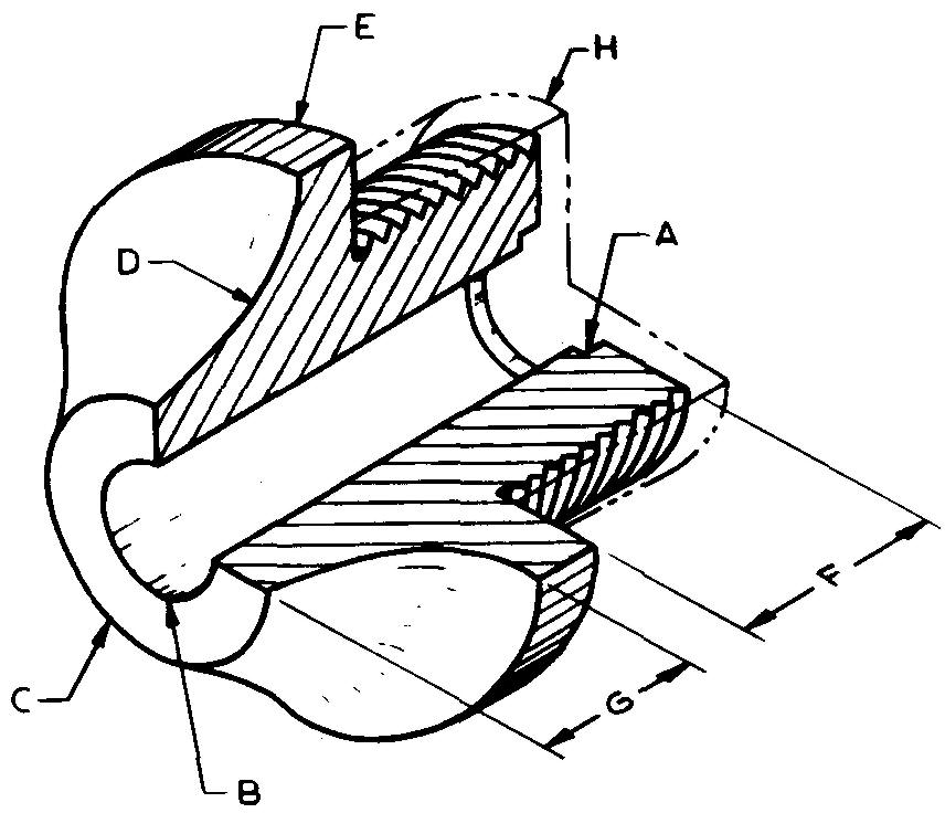
Sheet Size 8-1/2x11 Drawing Scale Twice
Material 1112 Steel Pieces per Unit 5
Final Part Size 1-5/16 lg
Heat Treatment Selective carburize, .010 thick
Hardness Test and Number Brinell (3000 KG) 207-212
References Sees. 8 (Polishing; Fig. 8-13), 9 (Rockwell Hardness Test), 11, 12 (Fig. 12-6), (Fig. 12-39,) and (Fig. 12-48); Table 8
Use detailed thread symbol for 1 "-20 UN ?-2 threads.
Specify "Polish all outside surfaces except threads and shoulder."
A — 5/8 bore, 1/8 deep, tolerance ±.005
B-3/8 ream
C-3/4dia
D-7/16R
E-1-5/8 dia
F - 5/8 G - 1/2
H — Threads must be soft, allow 1 /8 additional stock all around, remove after carburizing
Thread relief — 1/8 x 7/8 dia
problem 13-15 solenoid plate
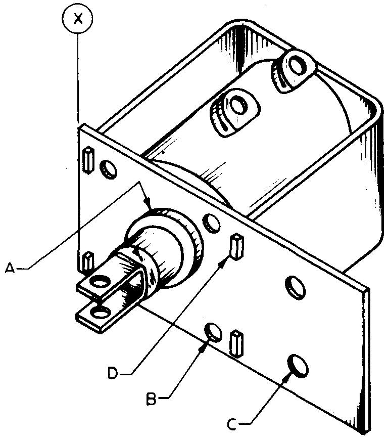
Sheet Size 8-1 /2 x 11 Drawing Scale Full
Material Aluminum #43 Pieces per Unit 30
Final Part Size #10 B & S ga x 2 wide x 4-1 /4 lg
References Sees. 12 (Fig. 12-8) and (Fig. 12-13); Tables 15, 43, and 65 Specify "Remove all burrs."
A — 1" dia punched hole, locate 1-1/2 from edge X and on center with 2" overall dimension
B — Drill and countersink for 4 #10 flathead machine screws, locate diagonally opposite on 1-1 /2 dia bolt circle
C — Drill and countersink for two 5/32 dia cooper's rivets, locate 1 " center to center and 3-1 /2 to the right of edge X
D — Slot, 1 /8 x 1 /4, 4 required, locate 1 -1 /4 on center left and right from hole A and 5/8 on center up and down from hole A
problem 13-16 trip lever
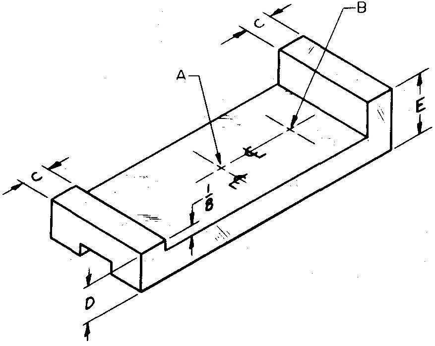
Sheet Size 8-1/2x11 Drawing Scale Optional
Material 3145 Steel Pieces per Unit 2
Final Part Size 1-3/8 wide x 3-7/8 lg
Heat Treatment Quench and temper
Hardness Test and Number 136° Diamond Pyramid 320-335
References Sees. 8 (Figs. 8-21 and 8-22), 9 (Quenching; Tempering), 9 (136° Diamond Pyramid), 11, and 12 (Fig. 12-4); Tables 6, 8, and 15 Parkerize finish.
Specify "Grind all over."
A- 13/16 drill
B — Clearance drill for #10-24 UN? machine screw, locate 1-1/16 from A
C - 3/8, tolerance +.002, -.000
D-1/2
E- 13/16 Through slot — 1 /2 wide, tolerance +.0025, -.0015, x 5/32 deep, central
problem 13-17 indexing plate
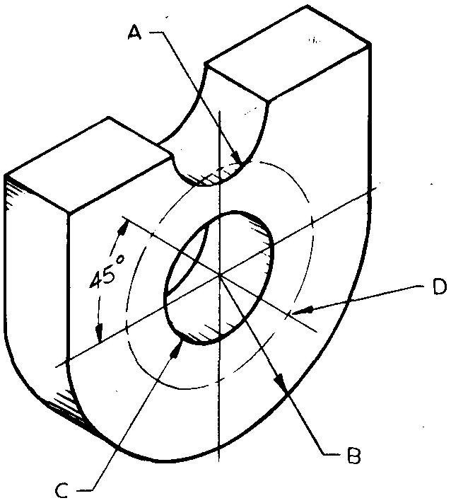
Sheet Size 8-1/2x11 Drawing Scale Full
Material 1020 Steel Pieces per Unit 1
Final Part Size 11/16 thick, tolerance +.002 Heat
Treatment Cyanide and harden, .015 thick
Hardness Test and Number Rockwell 30N 70-72
References Sees. 8 (Figs. 8-21 and 8-22), 9 (Liquid Carburizing), 11, and 12 (Fig. 12-48); Table 38 Grind flat sides and top surfaces.
Specify "Tolerance on all dimensions +0.0005, unless otherwise specified."
A — Use a 1 /2 R milling cutter B - 1-5/8 R
C — 1-1/8 ream, locate 1 -3/8 from top surface
D — 2 holes for #6 taper pin, located on 2 dia BC, (holes .310 dia at large end), use coordinate dimensions from hole C
problem 13-18 needle valve
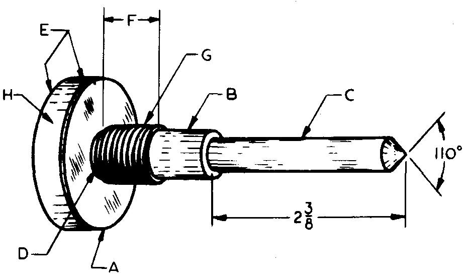
Sheet Size 8-1/2x11 Drawing Scale Twice Material Brass Pieces per Unit 15
Final Part Size 3-1 /4 lg
References Sees. 8.2 (Figs. 8-4 and 8-9), 11.7, 12.13, 12.15 (Fig. 12-36), and 12.25 (Fig. 12-56); Table 8
Use simplified thread symbol.
Specify "0.245 and 0.1875 dia and cone must be ground concentric within +0.0005 T.I.R."
Total Indicator Reading is the result obtained from an instrument known as a dial indicator gage. It is used to check the concentricity of the B and C diameters and the cone on the needle valve.
A — 1 " dia x7/32 lg
B — .245 dia, tolerance +.0025
C — .1875 dia, tolerance +.0015
D — Neck, 1/16 wide x 1/16 deep
E — Chamfer, 1 /32 x 45°
F — 5/16 to face
G — 5/16-24 UN?-2 threads
H — Fine knurl
problem 13-19 jaw plate
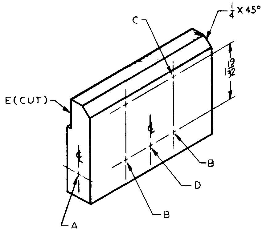
Sheet Size 8-1 /2 x 11 Drawing Scale Full
Material 1040 Steel Pieces per Unit 2
Final Part Size 3/4 thick x 2-3/4 wide x 4 lg
References Sees. 8 (Figs. 8-21 and 8-22), 12 (Fig. 12-4), and (Fig. 12-48); Tables 6 and 8 Parco-Lubrite finish. Specify "Grind all over."
A — 1 /4 ream from each side to holes B
B — 1 /2 ream through, 2 required, locate 1-5/8 center to center, equally spaced about center line of plate
C — 1/4-28 UN?-1 threads, 2 required, locate upper holes 13/32 from top surface
D — 3/8 drill through
E - 1/8 x 13/16 cut
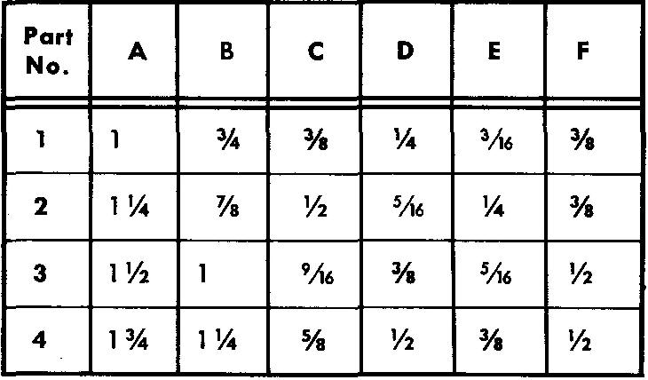
problem 13-20 c-washer
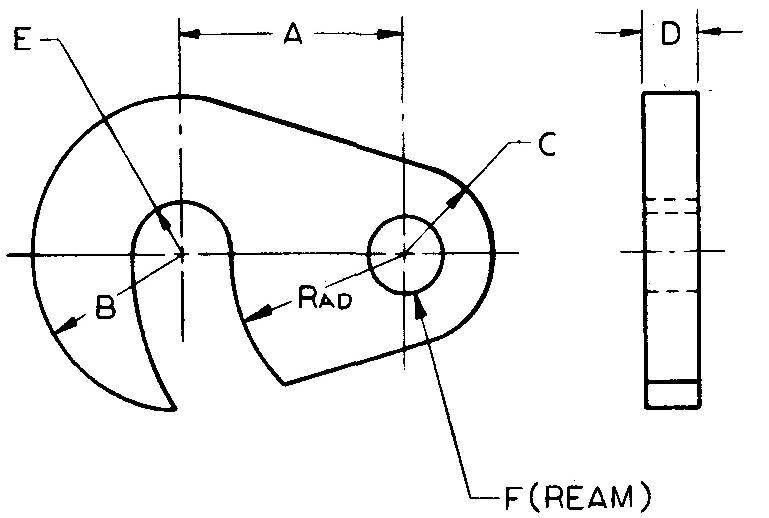
Sheet Size 8-1 /2 x 11 Drawing Scale Optional
Material 1065 Steel Pieces per Unit 12
Heat Treatment Quench and temper
Hardness Test and Number Rockwell C 42-44
References Sees. 8 (Figs. 8-21 and 8-22), 9 (Quenching; Tempering), 9 (Rockwell Hardness Test), and 12 (Fig. 12-48); Table 6 Blued finish.
Draw Parts 1 through 4 as directed.
Grind flat sides.
problem 13-21 plug
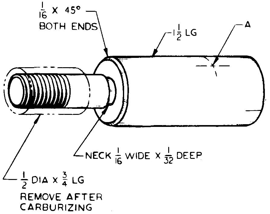
Sheet Size 8-1/2x11 Drawing Scale Optional Material 1025 Steel Pieces per Unit 3
Final Part Size 3/4 dia x 2-1 /2 lg
Heat Treatment Selective carburize, .008 thick
Hardness Test and Number Rockwell B 104-106
References Sees. 9 (Rockwell Hardness Test), 12 (Fig. 12-4), and (Fig. 12-36); Table 8 Use simplified thread symbol.
3/8-24 UN?-2 threads x 1/2 Ig, threads must be left in unhardened condition
A — 7/32 drill through, locate 1/2 from large end
problem 13-22 end plate
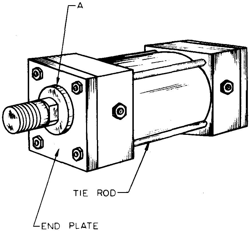
Sheet Size 8-1 /2 x 11 Material 1020 Steel
Drawing Scale Full Pieces per Unit 2
Final Part Size 1/2x4x4
References Sees. 8 through 8 (Figs. 8-21 and 8-22), 11, 12 (Fig. .12-6), and (Fig. 12-48)
Specify "Grind all over. Break all sharp corners."
Four tie rods, 3/8 dia, are spaced equally 3-1 /8 center to center
A — 1.000 ream through, 1-1 /2 dia bore, tolerance + .001, 9/32 deep from outside surface
problem 13-23 adjusting screw
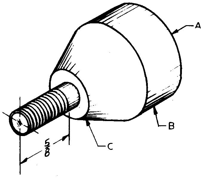
Sheet Size 8-1/2x11 Drawing Scale Optional
Material 1040 Steel Pieces per Unit 1
Final Part Size 1 -5/8 lg
References Sees. 8 (Fig. 8-4 and 8-9), 12 (Fig. 12-35), and 12(Fig. 12-56); Tables 6 and 8 Parkerize finish.
Use schematic thread symbol for the 1 /4-28 UN?-2 thread, 1/2 lg.
A - Chamfer, 1 /16 x 45°
B - 1 " dia x 1 /2 lg, medium knurl
C - 1 /2 dia
problem 13-24 adjusting lever
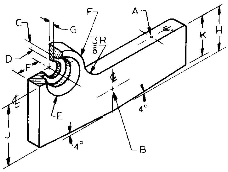
Sheet Size 8-1/2x11 Drawing Scale Optional
Material 1045 Steel Pieces per Unit 1
Final Part Size 5/16 thick x 3-1 /2 lg
References Sees. 10, 11, and 12 (Fig. 12-13); Tables 6, 8, and 15 Parco-Lubrite finish.
A — #10-24 UN?-2 threads, 1/2 deep, locate 11/16 from near end
B — Drill through and countersink (near side) for 1 /4 flathead machine screw, locate central with 3-1/2 and H dimensions
C — 5/8 dia
D —11/32dia
E — 1 /8 x 45° countersink
F — 1 /2 R, locate 3/4 up from hole B
G — .078, tolerance +.001
H — 15/16
Values for dimensions J and K must be calculated and applied to the detail drawing.
problem 13-25 shifter fork
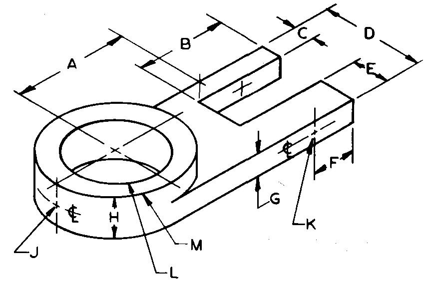
Sheet Size 8-1 /2 x 11 Drawing Scale Full
Material 1040 Steel Pieces per Unit 5
References Sees. 11, 12; Tables 6, 8, and 12 Blued finish.
All dimensions should be in decimal form to two decimal places.
Drawing should include a general note stating: "Tolerances on all dimensions + 0.0156 unless otherwise specified."
A — 3-1/8
B — 2-1/2
C — 5/8
D — 2"
E — 3/4
F — 1-1/8
G — 5/8
H — 1-1/8
J — 3/8-? UNC threads
K — J drill, through
L — 2-1/2 dia, tolerance ±.002 M -2-7/8 dia
problem 13-26 jaw block
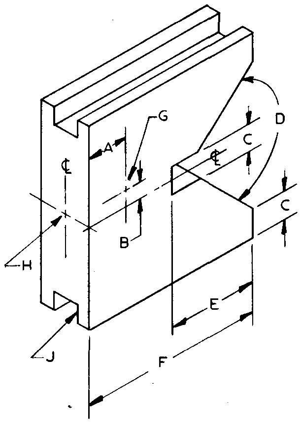
Sheet Size 8-1 /2 x 11 Drawing Scale Full
Material Aluminum Pieces per Unit 2
Final Part Size 3 /4 thick x 2-3/4 lg
References Sees. 11, 12, and 12 ; Tables 6 and 12 Annodize finish.
All dimensions should be in decimal form to two decimal places.
Drawing should include a general note: "Tolerances on all dimensions ±0.0156."
A-9/16 B-7/32 C - 3/8
D - 90° E-1-1/4 F-2-1/2
G — #30 drill, through
H — .4375 ream, 7/8 deep
J — Slots, 3/8 wide x 9/32 deep
