Principles of detail drawings
The detail drawing
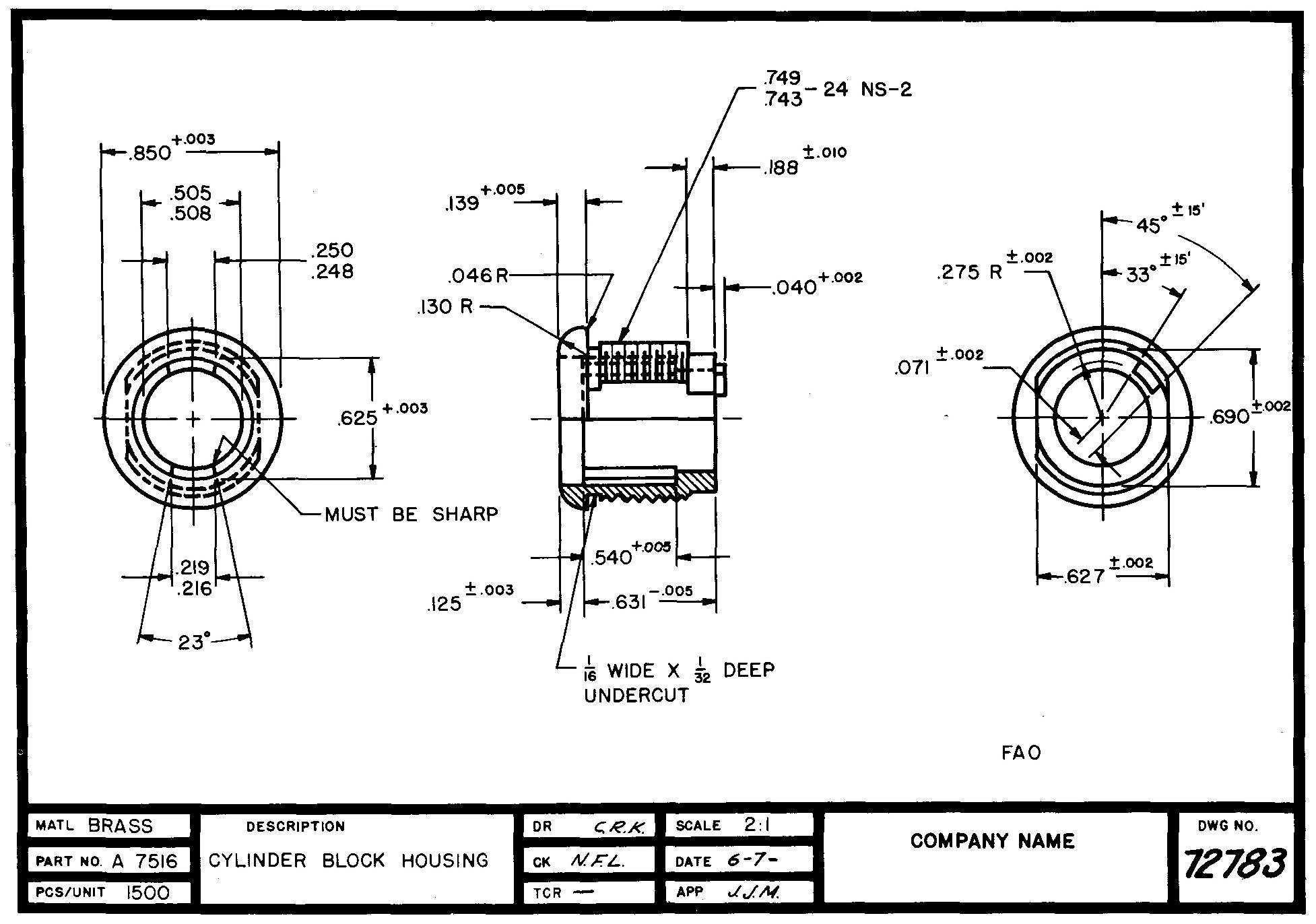
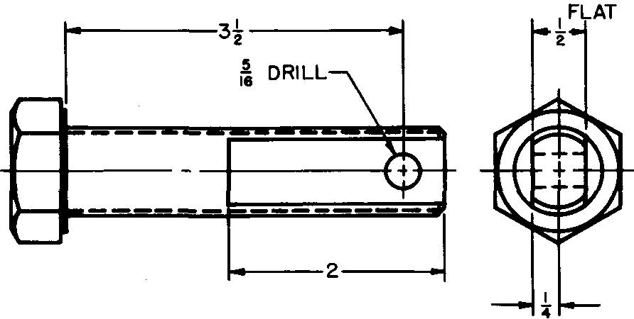
Figure 3-1 illustrates the detail drawing.
Fig. 3-1. A detail drawing
The three views show how one machine part will look when completed. It accurately describes the size and the shape of the machine part. It warns the shopman of any special features of the part which should be made to a precise size. The drawing gives complete directions for everything the shopman needs to make the part.
It specifies the material from which the part will be made and, if necessary, tells how hard the metal from which the part is made must be when the part is ready for use. It guides the selection of those machine processes which will be used to make the part.
Many detail drawings indicate the special tools and cutters which may be required to make the various cuts shown on the part (see Fig. 1-3 section The industrial drafting room).
Symbols are placed on the drawing to show which surfaces must be smoothed and which surfaces may be left rough. Detail drawings list the quantity of parts required, the scale and date of the drawing, the name of the draftsman, and the name of the checker.
In short, the detail drawing serves as an accurate and permanent description of the required part.
Selecting the views
Before drawing the views of a machine part, many machine draftsmen prepare a quick freehand sketch as described in section Technical sketching. The sketch is used as a guide in the selection and placement of the views on the sheet.
Often, views of parts may be traced directly from the assembly drawing, such as Fig. 17-1 section Principles of assembly drawings.
When this is done, a sketch is unnecessary. Tracing the views usually saves drafting time, especially when the views describe complicated parts.
In earlier courses in mechanical drawing, you have learned that there are six principal views of an object. These are the top, bottom, right-side, left-side, front, and rear views. Rarely, if ever, is it necessary to show all six views of a part on one drawing.
Only the views which will show all of the features of the part in the clearest possible manner should be selected. In Fig. 3-2, views C, D, and F are considered the best views to describe this particular part.
Fig. 3-2. The six principal views of an object
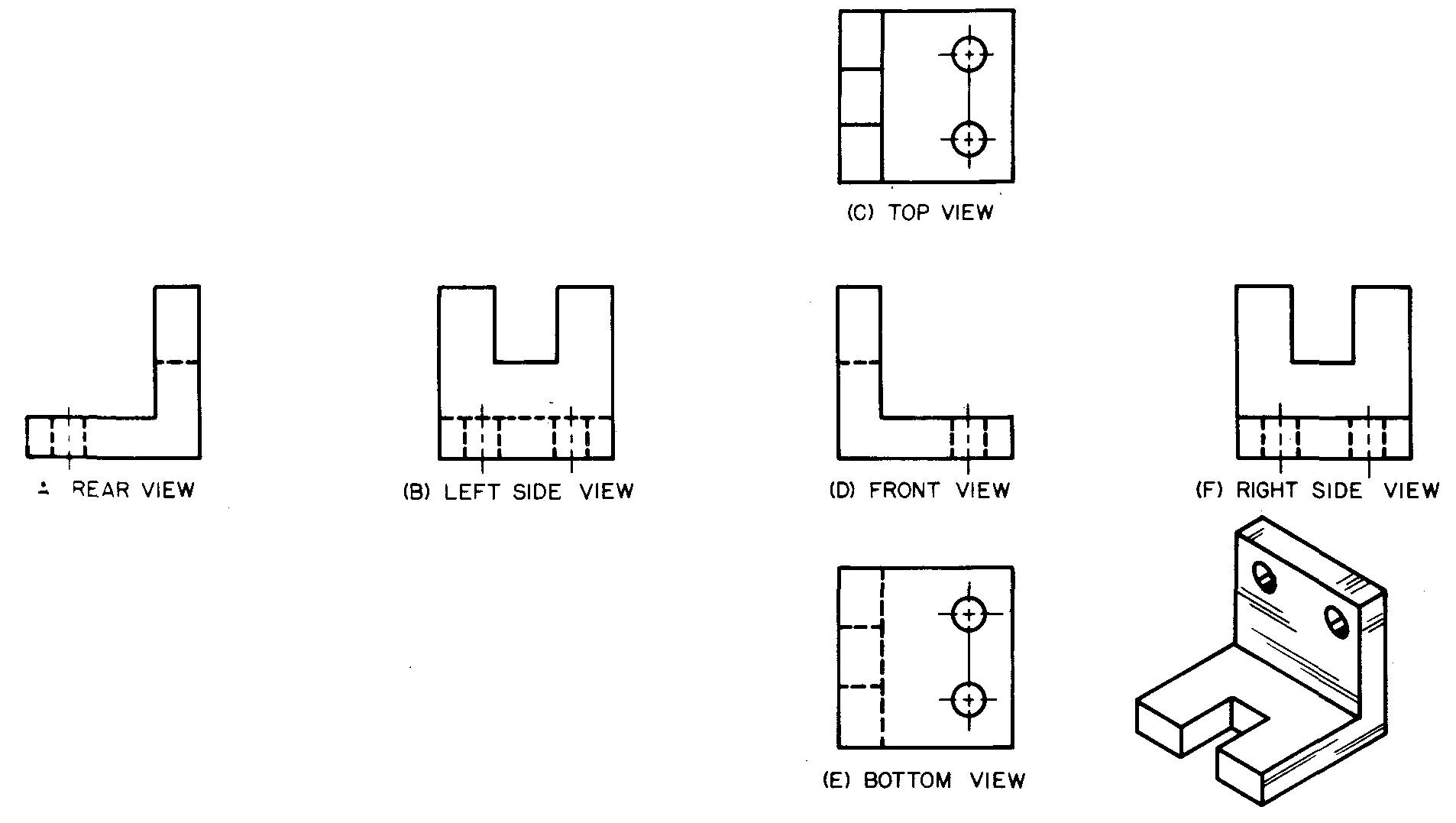
Can you see why these views were selected instead of the others?
It is always wise for the draftsman when drawing views of parts to consider all of the six principal views and then make his choice accordingly.
Number of views
A detail drawing should show the part as simply and clearly as possible. It should never contain unnecessary views or information. The draftsman should make a thorough study of all of the features of the part before selecting the number of views he will draw.
The features of the part are understood to mean the lines which show the outline and shape of the various cuts, holes, and surfaces which make up the structure of the part.
Never try to reduce drafting time or to save space on a drawing by omitting features of a part, for these may be needed for complete understanding.
Some parts may be completely described in one view. This is particularly true for cylindrical or simple flat parts such as the parts shown in Fig. 3-3.
Fig. 3-3. One-view drawings
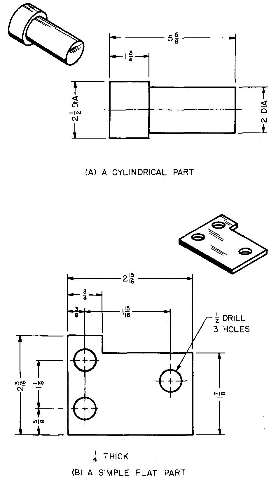
When only one view of a cylindrical part is drawn, the notation DIA or D should be added to all diameter dimensions.
Thus, the shopman is assured the part is completely cylindrical. The thickness of the part should be given below the view on a one-view drawing of a flat object.
Figure 3-4 shows how the wise selection of two views will often result in adequately describing every feature of a part. The right-side view is unnecessary in this example.
Fig. 3-4. A two-view drawing
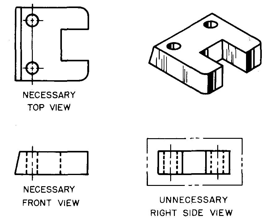
In some cases, however, depending upon the general shape of the part, two, three, or more views may be necessary, together with auxiliary and sectional views.
Spacing and placing the views
It is important that the draftsman be careful in spacing and placing the views on the detail drawing. Crowded views or views too widely spaced are misleading and confusing to read.
Before drawing the views of a part, the draftsman should carefully study the space available. He should then compare the size of the space on the drawing sheet with the size required for the views.
Views of a simple object may be drawn as close as 1 to 1-1/2 inches apart. Views of more complicated parts, however, require wider spacing so that all the dimensions and notes may be placed on the drawing without crowding.
These may be placed between and outside the views.
Views should be lightly blocked in at first to test the general arrangement and balance within the given space on the sheet. Experienced draftsmen tell us that with practice you can improve your ability to space views rapidly and neatly.
Cylindrical parts are usually drawn with the long axis (or center line) in a horizontal position on the sheet.
Figure 3-5 shows the preferred or usual position of the views.
Fig. 3-5. Two views of a cylindrical part
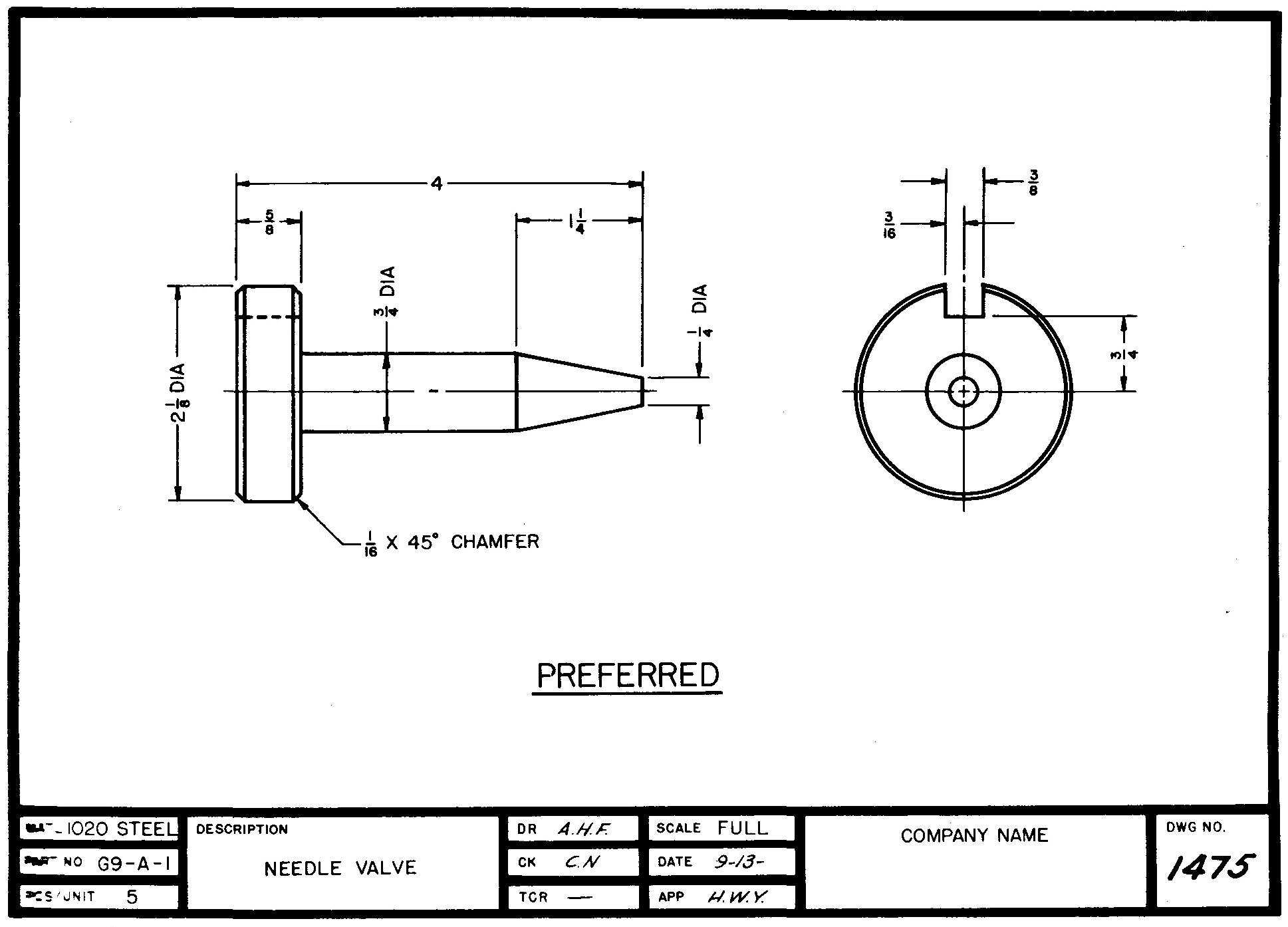
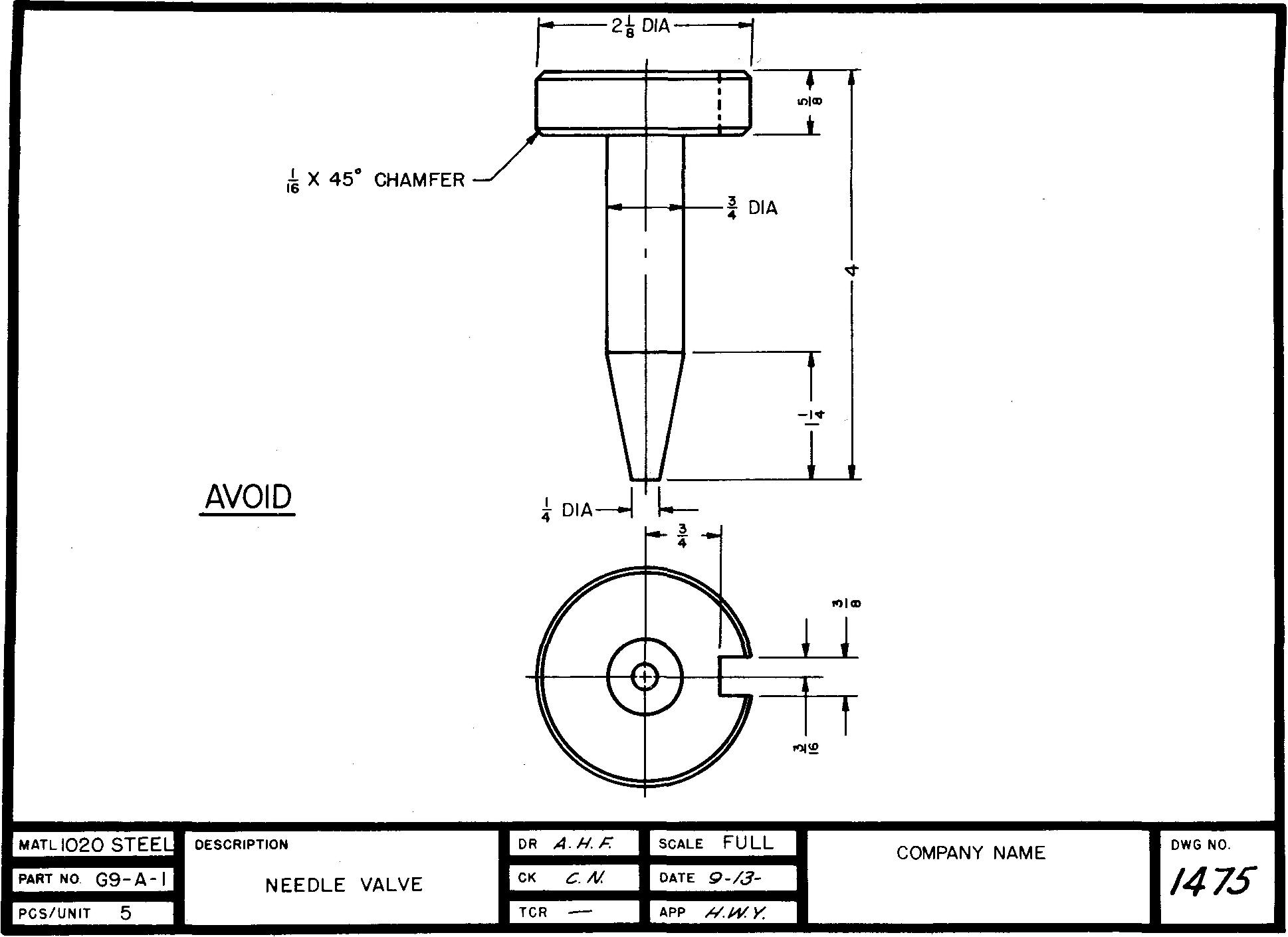
Figure 3-6 shows the alternate position which is used only in special cases.
Fig. 3-6. Alternate position for the two views of a cylindrical part
Whenever practical, draftsmen draw the noncylindrical parts in the same relative position as they appear when finally assembled with other parts in the complete mechanism or structure.
Figure 3-7 illustrates good view spacing.
Fig. 3-7. Good view spacing
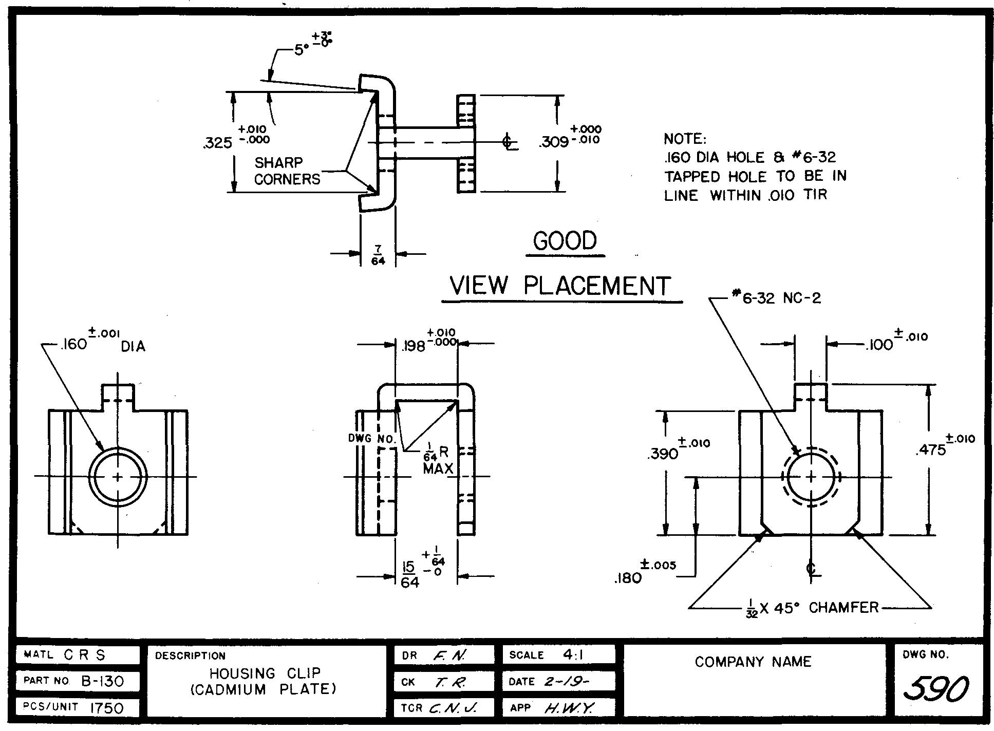
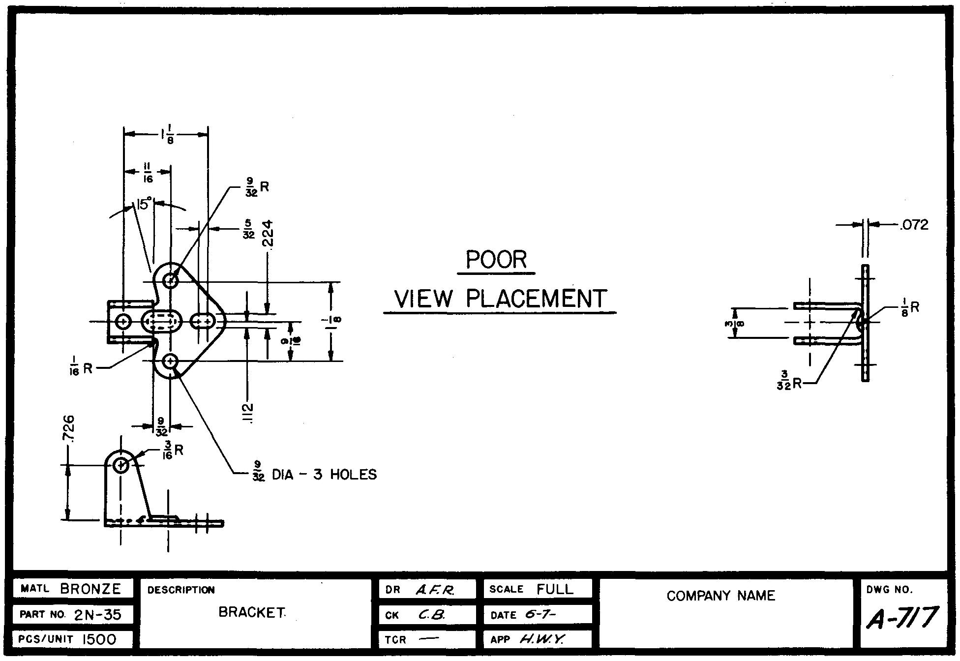
There is adequate space around and between the views for the dimensions and notes. In Fig. 3-8, the dimensions and notes are crowded because of the poor placement of views.
Fig. 3-8. Poor view spacing
Selecting the scale of detail drawings
Detail drawings should be drawn full size whenever possible.
Small parts, however, are often difficult to show clearly if drawn full size. In this case, the scale may be enlarged to 2:1 (twice size), 4:1 (four times size), 10:1 (ten times size), or even 20:1 (twenty times size).
If the part is exceptionally large, it may be reduced to 1:2 (half size), 1:4 (quarter size), and so on.
The scale 3:1 (three times size) or 1:3 (one-third size) is not recommended, since 1/3 divisions on the scale make measurements too difficult.
Parts with thin sections, such as continuous long rods, bars, and links, may not fit on the sheet if drawn full size.
If the scale is reduced, the shape of the cross section is often difficult to draw clearly. It is common practice to draw such parts full size but with a break to shorten the overall length.
The cross sectional shape still shows (Fig. 5-34 section Conventional representation).
Standard parts
In the design of a mechanism or structure, designers try to select and use as many standard parts as possible. (Standard parts are parts which are commercially available and which can be used as purchased.)
It is generally less expensive to purchase a readily available standard part than to have the shop make it. Such parts include springs, nuts, bolts, washers, keys, cotter pins, dowel pins, pipe fittings, handles, oil and grease fittings, taper pins, bushings, and bearings.
The Tables contains descriptions of many of these standard parts.
Parts such as these are usually installed in the mechanism or structure without changing the original shape.
Altered standard parts
These are purchased parts which must be changed, or adapted, to the design. Parts such as these usually require only slight alterations. Generally a simplified drawing is made of the part.
This drawing shows in detail only those features which require changing in the shop, as in Fig. 3-9.
Fig. 3-9. An altered standard part
It is not necessary for the draftsman to make a completely detailed drawing of a part which has been previously manufactured.
Manufactured parts
These are parts of a structure or a mechanism which must be formed by primary operations such as casting, forging, stamping, and welding.
These parts may also require secondary machining operations such as drilling, milling, and turning or final operations such as painting, plating, and heat treatment.
Since the parts usually cannot be purchased in the required form, they are made in the shop from detail drawings prepared by draftsmen in the engineering department.
Manufactured parts include shafts, housings, collars, bases, brackets, special cams, and so on.
Arranging the parts on a sheet
Frequently, when only a few parts must be manufactured, several different parts may be drawn on one sheet. In cases of large quantity production of parts, it is considered good practice to draw only one part per sheet.
When the manufactured part is a large casting or a welded fabricated part, most companies prefer to have the detail drawings prepared on one sheet. Company rules should always be carefully studied and followed.
Drafting practice varies slightly with different companies, and it is important for the draftsman to learn the rules of his own company.
If drawing the views of several different parts on one sheet is considered appropriate, the draftsman should select, if possible, those parts which are related, or mated.
Examples of such parts include shafts and bushings, gears which fit together, and mating (matching) threaded parts.
In addition, parts which are formed by the same process are often grouped together on one sheet. For example, shopmen will find it helpful if all welded parts are grouped together on the same sheet.
Other sheets might show all castings, all sheet-metal parts, all nonmetallic parts (rubber, fiber), and so on.
When two or more parts are drawn on the same sheet, it is important to space the views far enough apart to prevent the dimensions and notes of one part from interfering with those of another.
Some companies box in the views to separate one part from another, as shown in Fig. 3-10.
Fig. 3-10. Separating views of parts by boxing in
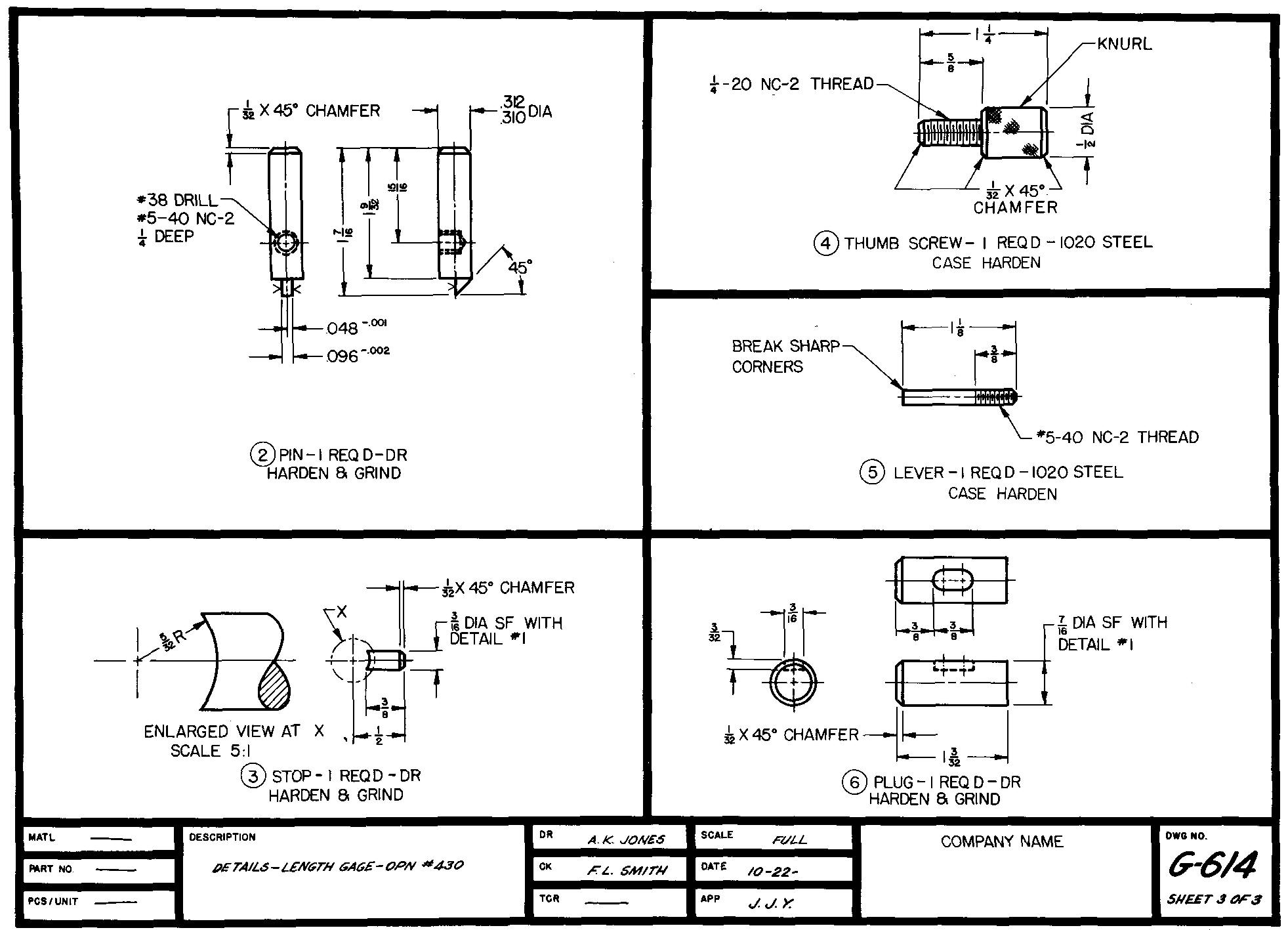
It is considered good practice to use the same scale for all parts drawn on one sheet. When this can be done, the scale given in the sheet title block should then apply to all of the parts drawn on the sheet.
If it is necessary to draw the various parts to a different scale, the scale is indicated near the views of the parts and the sheet title box records this fact. In some cases an enlargement may be drawn for a portion of the view.
The scale for the enlargment is indicated near the enlarged view as shown in Fig. 3-10.
The detail title
In many companies, a separate title is used to identify each part on the sheet, as shown in Fig. 3-10. The title is lettered directly below the views of the part.
It is frequently underlined for emphasis. The title usually consists of the part name and number, the quantity of identical parts the shopman is required to make, and the kind of material to be used.
If necessary, the stock size, pattern number, required heat treatment, and the type of surface finish are also indicated.
Each different part of the mechanism is assigned a number. The part number is placed in a circle to the left of the detail title. This circle, referred to as a balloon, is also shown in Fig. 3-10.
The balloon circle may have a diameter of 1/4, 3/8, or 1/2 inch. Part numbers may also be arranged as shown in Fig. 3-9.
Review questions (The answers are not given)
1. What is the purpose of a detail drawing!
2. How is a freehand sketch used to assist the draftsman in preparing a detail drawing?
3. What requirements guide the draftsman in selecting the number of views he will draw of a machine part?
4. What is meant by the features of a part?
5. What are some of the disadvantages of crowded views?
6. How closely may the views of a simple object be spaced?
7. What is meant by lightly blocking in the views?
8. Whenever possible, detail drawings should be drawn to what size?
9. Small parts are often drawn to an enlarged scale. What size drawing scales are often used for enlargement?
10. Why is the scale one-third size not recommended?
11. Define the term manufactured' parts. Are detail drawings prepared for these parts? Explain.
12. Define the term standard parts. Are detail drawings usually prepared for these parts? Explain.
13. What conditions govern how the parts are selected when drawing more than one part on the same sheet?
14. What is the advantage of drawing more than one part on a sheet?
15. Should all parts drawn on the same sheet be drawn to the same scale? Explain.
16. What is meant by a detail title! What information does it include?
17. What is meant by a balloon! What are the usual diameters used for balloon circles?
Problems: technical sketching and principles of detail drawings
On 8-1/2 x 11-inch paper, prepare freehand technical sketches of the following problems. You may use plain paper or cross section paper as described in Sec. Technical sketching.
Read the problem statements carefully since certain features of the parts have been intentionally omitted on the illustrations.
Estimate all omitted sizes. Space the views far enough apart to allow room for the required dimensions and notes. These will be applied to the views after you have studied section Principles of dimensioning and Principles of notation. Keep your sketches for this purpose.
Group 1 one-view sketches
problem 3-1 Use Problem 13-12.
problem 3-2 Use Problem 13-15.
problem 3-3 Use Problem 13-17.
problem 3-4 Use Problem 13-20.
problem 3-5 Use Problem 13-22.
problem 3-6 Use Problem 14-4.
problem 3-7 Use Problem 14-10.
problem 3-8 Use Problem 14-11.
problem 3-9 Use Problem 15-17.
problem 3-10 Use Problem 15-37.
problem 3-11 Use Problem 15-40.
problem 3-12 Use Problem 15-41.
Group 2 two-view sketches
problem 3-13 Use Problem 13-1.
problem 3-14 Use Problem 13-8.
problem 3-15 Use Problem 13-10.
problem 3-16 Use Problem 13-16.
problem 3-17 Use Problem 13-19.
problem 3-18 Use Problem 14-13.
problem 3-19 Use Problem 14-14.
problem 3-20 Use Problem 14-30.
problem 3-21 Use Problem 15-18.
problem 3-22 Use Problem 15-29.
problem 3-23 Use Problem 16-4.
problem 3-24 Use Problem 16-6.
problem 3-25 Use Problem 16-10.
Group 3 three-view sketches
problem 3-26 Use Problem 13-6.
problem 3-27 Use Problem 13-11.
problem 3-28 Use Problem 13-24.
problem 3-29 Use Problem 14-16.
problem 3-30 Use Problem 14-28.
problem 3-31 Use Problem 15-10.
problem 3-32 Use Problem 15-22.
problem 3-33 Use Problem 16-11.
problem 3-34 Use Problem 16-13.
problem 3-35 Use Problem 17-1, Part A.
problem 3-36 Use Problem 17-5, Body.
problem 3-37 Use Problem 17-14, Detail AC-386.
problem 3-38 Use Problem 17-14, Detail AC-390.
problem 3-39 Use Problem 17-16, Leg.
problem 3-40 Use Problem 17-20, Detail AC-243.
problem 3-41 Use Problem 17-21, Detail 3.
problem 3-42 Use Problem 17-21, Detail 6.
problem 3-43 Use Problem 17-21, Detail 7.
Group 4 two or three-view sketches Omit dimensions and notes.
problem 3-44 Door hinge, one leaf only.
problem 3-45 Wall switch plate, triple switch.
problem 3-46 Pencil sharpener crank arm.
problem 3-47 Door knob.
problem 3-48 Hexagonal nut, semi finished. See Table 13.
problem 3-49 Machine screw, flat head. See Table 15.
problem 3-50 Shoulder screw, socket head. See Table 16.
problem 3-51 Flanged tee, cast iron. See Table 75.
problem 3-52 90° ell, cast iron, flanged. See Table 75.
problem 3-53 Filing cabinet drawer pull.
problem 3-54 Octagonal cold chisel.
problem 3-55 C-clamp frame.
problem 3-56 Lathe dog.
problem 3-57 File handle.

![]()