Principles of dimensioning
Introduction
Thus far, we have illustrated ways to best describe the shape of machine parts. In this section and in the next, we shall discuss the various techniques necessary for describing the size of machine parts.
The complete shape and size description must be shown on the drawing before a part may be produced.
The tools of size description are known as dimensions (which are discussed in this chapter) and notes (which are discussed in section 7. Principles of notation).
Considerable engineering judgment and experience is required for accurate size description. The machine designer or draftsman should be as familiar as possible with materials, methods of manufacturing, and shop processes.
It is important that the draftsman learn as much as possible about the requirements of the part which is shown on the drawing in its completed condition.
Parts of this text will help the student draftsman develop this engineering judgment. Fundamental to this study is the fact that the shopman should not be required to calculate any needed size nor should it be necessary for him to measure the drawing or to assume the size for any omitted dimension.
Dimension lines
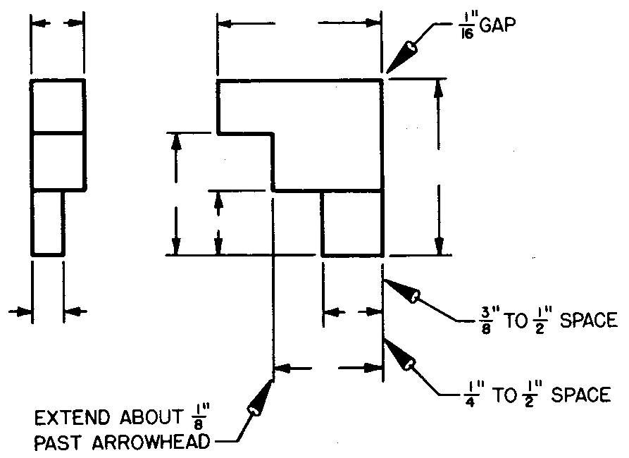
As shown in Fig. 6-1, dimension lines should be located at least 3/8 inch to 1/2 inch away from the views.
Fig. 6-1. Dimension and extension lines
Parallel dimensions drawn along the edge of a view may be spaced from 1/4 inch to 1/2 inch apart. Dimension lines are spaced by eye and are not measured.
A good rule is to keep the
dimensions off the views whenever possible. Dimension lines should never be
drawn through figures. Avoid crossing two or more dimension lines.
Extension lines
The gap or space between extension lines and the view should be approximately 1/16 inch (see Fig. 6-1).
The extension line should extend approximately 1/8 inch beyond the point of the arrowhead. Failure to make neat extension lines may cause the drawing to appear ragged and untidy.
Avoid crossing extension or dimension lines with each other. To reduce the number of crossings, draw the shortest dimension lines nearest the view, the next longest parallel to the first, and so on.
Center lines
The axis, or precise center, of cones, cylinders, and other solids is represented by the center line. The center of a circle is located by the intersection of two center lines drawn perpendicular to each other.
The center line is a thin line consisting of alternate long and short dashes, as shown in Fig. 6-2.
Fig. 6-2. Center lines
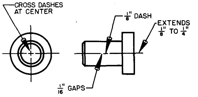
Each gap or space between the dashes is approximately 1/16 inch long. For long center lines, the spaces and dashes may be made slightly longer. Center lines should extend approximately 1/8 inch to 1/4 inch beyond the edge of the view.
In Fig. 6-3, center lines indicate the centers from which the arcs are drawn.
Fig. 6-3. Continuous center lines
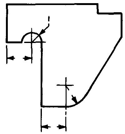
A radial line is drawn to the curve from the point where the center lines cross. In this special case, short center lines are often drawn as continuous thin lines, omitting the dashes and gaps.
When two perpendicular center lines are drawn for a circle, it is a good practice to cross the two short dashes at the center, as shown in Fig. 6-2.
However, the short dashes should not cross when more than two center lines are drawn through the center of a circle, as shown in Fig. 6-4. More than two intersecting dash lines make the actual center point of the circle difficult to locate.
Fig. 6-4. Center lines for circles
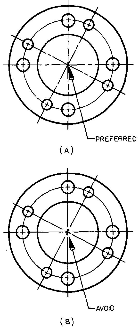
The circular lines indicating the centers of the small circles in Fig. 6-4 are another kind of center line. This circle is called a bolt circle.
Arrowheads
The ends of a dimension line are identified by arrowheads. Two acceptable methods of drawing arrowheads are shown in Fig. 6-5.
Fig. 6-5. Arrowheads
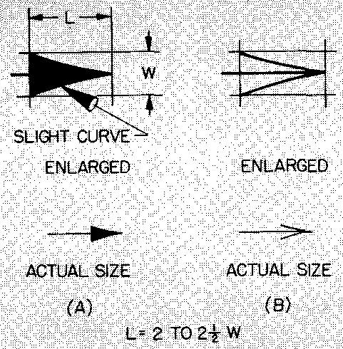
The length of the arrowhead should be approximately 1/8 inch. Its length should be roughly 2 to 2-1/2 times the width.
The point of the arrowhead should touch the extension line, as shown in Fig. 6-1. All arrowheads on a drawing should be made to approximately the same size. They should be dark enough to be readily visible.
Figures
Figures on a machine drawing must meet two important requirements.
The figures must be legible and the draftsman must be able to make them rapidly and with ease. There are two approved styles of figures: inclined and vertical. Samples of both styles of figures are shown in Fig. 6-6.
Fig. 6-6.
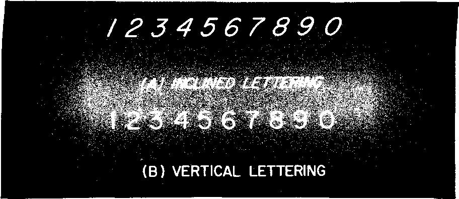
All figures on one drawing should be the same style.
Figures (whole numbers) for dimensions on a drawing should be 1/8 inch high. Figures for numerators and denominators are usually about 3/4 as high as the whole number.
The total height of a fraction is approximately 5/16 inch, as shown in Fig. 6-7.
fig. 6-7. characteristics of figures
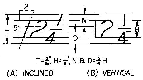
Inclined figures are slanted in the proportion of 2 units to 5 units. The slant is shown in Fig. 6-7A. It is advisable to draw light guide lines for all figures, thus insuring uniformity of the height and of the slant for each figure on the drawing.
Feet and inch symbols
The symbol for inch (") and the symbol for foot (') are used in the dimensioning of machine drawings when the units of measure are required. If all of the dimensions on a drawing are in inches, the symbol after the figure is omitted.
Although the inch symbol is frequently omitted, many companies use it for one-inch dimensions and for notes, such as 1" or 1" DRILL.
Feet and inch symbols are usually used in combination for dimensions measuring over 72 inches. Dimensions for feet and inches are expressed as 7'- 10 1/2". Feet and inches figures are always separated by a dash.
Selection of dimensions
Detail drawings should contain only those dimensions which the shopman needs to make the part.
However, if there is the slightest likelihood that he may not thoroughly understand what is required from the given dimensions, it is always better to give an additional dimension. Dimensions for the same feature of the part should be given only once.
Some parts may contain several identical features such as fillets, rounds, slots, and holes which are of the same size. Here it is permissible to dimension one typical condition and omit all other dimensions of like nature, as shown in Fig. 6-8.
Fig.6-8. Dimensions for typical or repeated features
Nothing should be left to chance or guesswork on a drawing. Drawings of parts should be dimensioned so there will be no possibility of questions. A shopman is not permitted to work to a size which he determines by measuring the drawing. So important is this rule that many companies stamp or print "Do not scale this drawing" on each drawing sheet.
Placement of dimensions
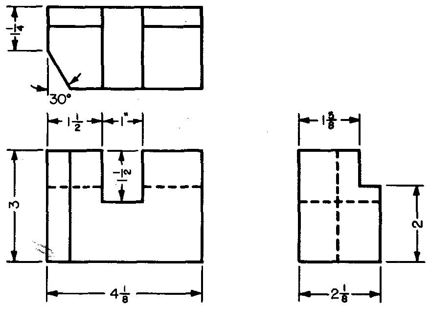
Dimensions should be carefully positioned on a drawing. A good policy is to place dimensions near the view which shows the profile (or contour) of the feature being dimensioned. The placement of the dimensions in Fig. 6-9 illustrates this principle.
Fig. 6-9. Placement of dimensions
Aligned dimensions
For ease of reading, all dimension figures on a drawing must be arranged according to some system. In the aligned dimensioning system, the draftsman places all figures so that they are read from either the bottom or the right side of the drawing.
This system is shown in Fig. 6-10.
Fig. 6-10. aligned dimensions
In this system, the division line for fractions is always drawn in line with the dimension line. All figures are placed at right angles (90°) to the dimension line, approximately in the center of the line.
If a center line extends through an area where a figure is planned, the figure may be moved off center on the dimension line. The aligned system of dimensioning is widely used in machine drawing.
Unidirectional dimensions
Dimension figures may also be arranged according to the unidirectional dimensioning system. In this system all figures are placed so as to be read from the bottom of the drawing, as shown in Fig. 6-11.
Fig. 6-11. Unidirectional dimensions
This system is widely used in the aircraft, automotive, and shipbuilding industries, as well as in other industries where large drawing sheets are often used.
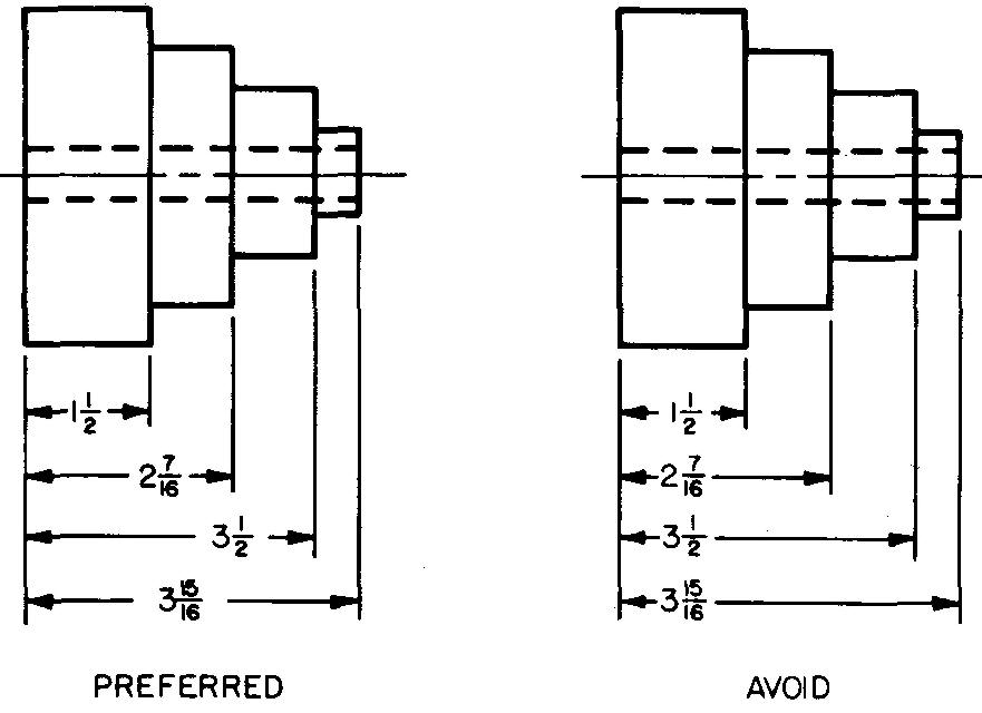
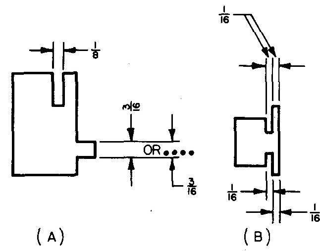
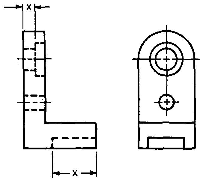
Tie-up, or duplicate, dimensions
Avoid giving two or more dimensions which, when added together, equal another dimension on the drawing. Dimensions such as these are often called tie-up, or duplicate, dimensions.
Standard shop practice permits the shopman to vary the size of a feature of the part by 1/64 inch (or some other specified amount) when he is working to a fractional dimension on a drawing.
For example, the fractional dimensions X and Y shown in Fig. 6-12A could each be made larger or smaller. If they were made larger, each would be 33/64 inch long instead of 1/2, or 32/64, inch.
Fig. 6-12. Tie-up, or duplicate, dimensions
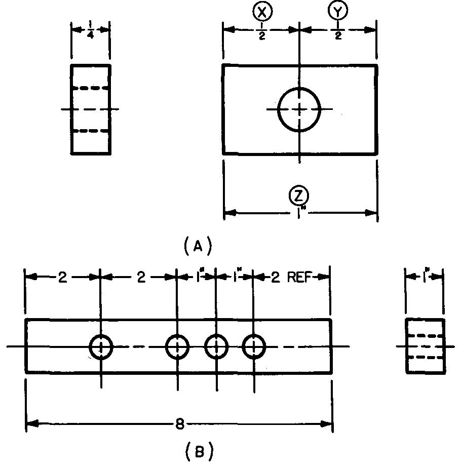
Even if the shopman were to enlarge dimension Z by the same amount ( + 1/64 inch), making Z 1-1/64 inches, this would not equal the total length of the sum of dimensions X and Y. In this example, either dimension X or dimension Y should be omitted.
If it is considered absolutely necessary to give the tie-up, or duplicate, dimension, the dimension should be labeled REF, meaning reference, as shown in Fig. 6-12B. The reference dimension would be used by the worker only as a check. It would not be used to lay off a measurement.
Overall dimensions
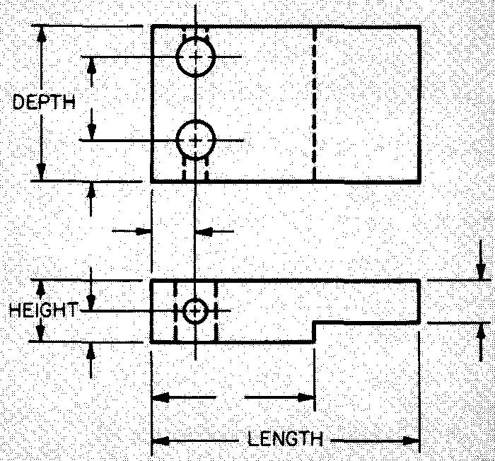
Length, height, and depth dimensions are called overall dimensions. The overall dimensions are placed outside the shorter dimensions, as shown in Fig. 6-13.
Fig. 6-13. Overall dimensions
Staggering dimension figures
When there are several parallel dimension lines, the figures should be staggered, as shown in Fig. 6-14, so they will not interfere with each other or run together.
Fig. 6-14. Staggered dimension figures
Staggering dimension figures
When there are several parallel dimension lines, the figures should be staggered, as shown in Fig. 6-14, so they will not interfere with each other or run together.
Dimensioning from finished edges
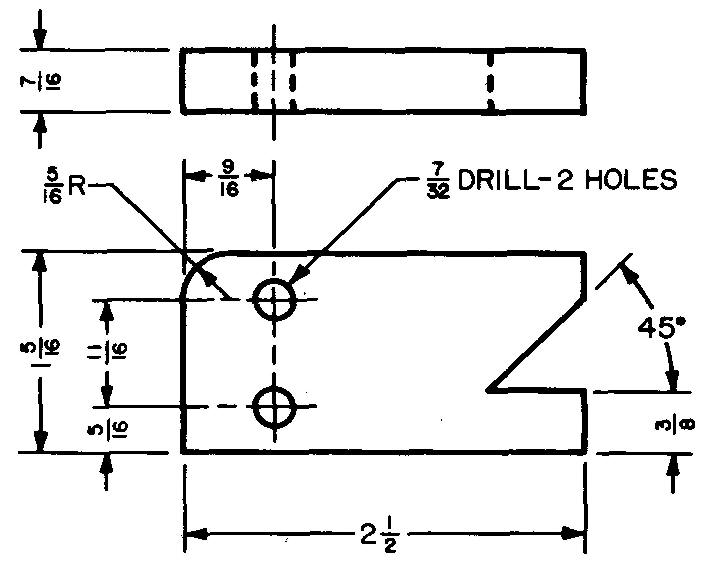
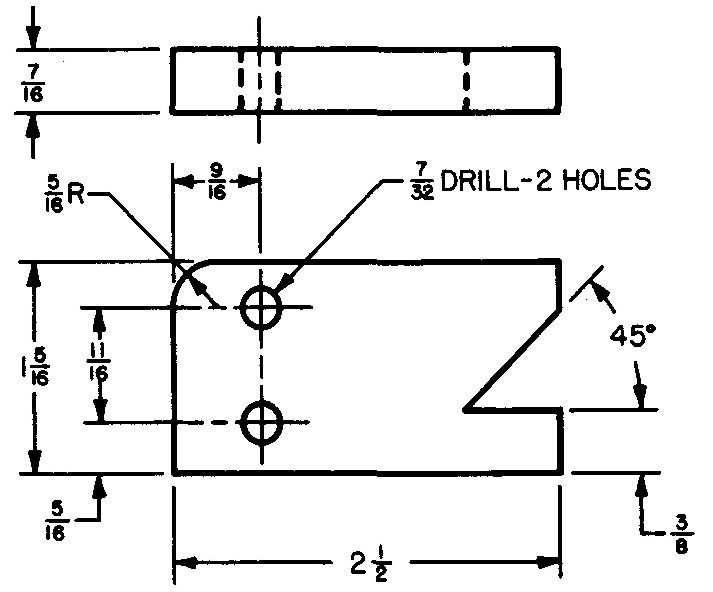
For precision work, finished or machined edges are used as base lines from which all dimensions are measured, as shown in Fig. 6-15. The base lines are usually at right angles to each other.
Fig. 6-15. Dimensioning from finished edges
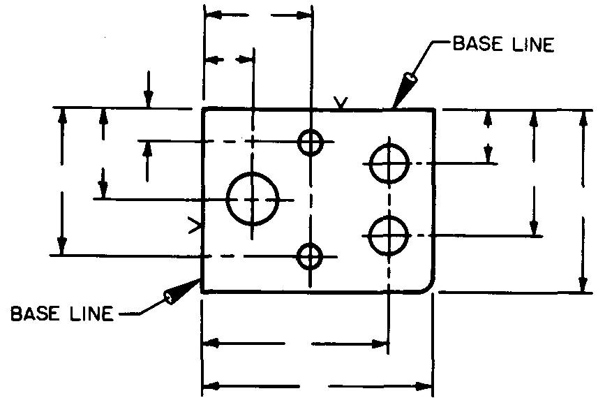
When all dimensions are measured from the base lines, the shopman is less likely to make errors. If the accuracy of one dimension depends upon the accuracy of the preceding one, errors often accumulate.
For example, suppose the shopman were laying out a series of holes along one center line as in Fig. 6-12B.
As this drawing is dimensioned, the location of each hole is figured from the hole to its left.
If an error in measurement were made, each hole to the right of this error would be out of position. When each dimension is measured from a base line, as shown in Fig. 6-15, an error made in one measurement does not affect the other measurements.
In some companies, if the part does not have finished edges, it is permissible for the draftsman to specify machining along two edges, preferably at 90° to each other, solely for the purpose of accurate shop layout. The finished edges of the part would thus serve as the base lines.
Dimensioning from a location hole
The center lines of a selected hole may also be used as base lines.
The hole, called a location hole, may be used as a starting point for dimensioning, as shown in Fig. 6-16.point for dimensioning, as shown in Fig. 6-16.
Fig. 6-16. Dimensioning from a location hole
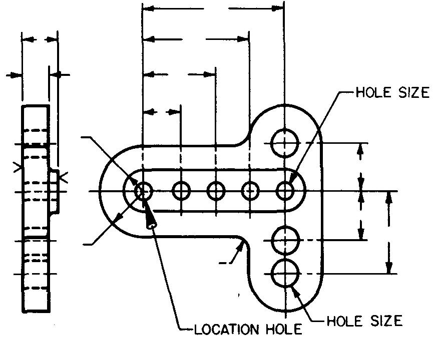
All other holes and other important features of the part are thus located from the hole. Usually, one of the required holes on the part is used for location.
In special cases, however, a hole is produced solely for use as a location hole in some convenient position on the part.
Of course, after the part is assembled with the other parts in the product, such a location hole is not used. Location holes are usually used when conditions require precise layout.
Dimensioning circles
The abbreviation D, or DIA (see Fig. 6-17), is used to indicate the diameter of a circle.
Fig. 6-17. Diameter dimensions
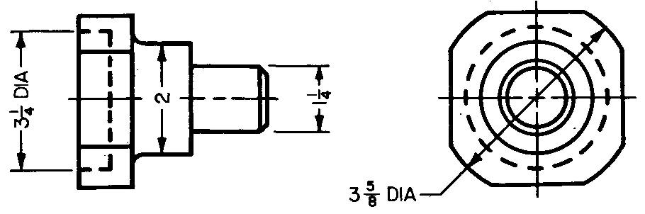
It is especially important to use this abbreviation for one-view drawings of cylindrical parts, such as the part shown in Fig. 3-3 Principles of detail drawings, and for internal diameters (holes), since in these cases confusion might result from its omission.
If the part is obviously cylindrical, the abbreviation may be omitted.
Dimensioning hole spacings on a circle
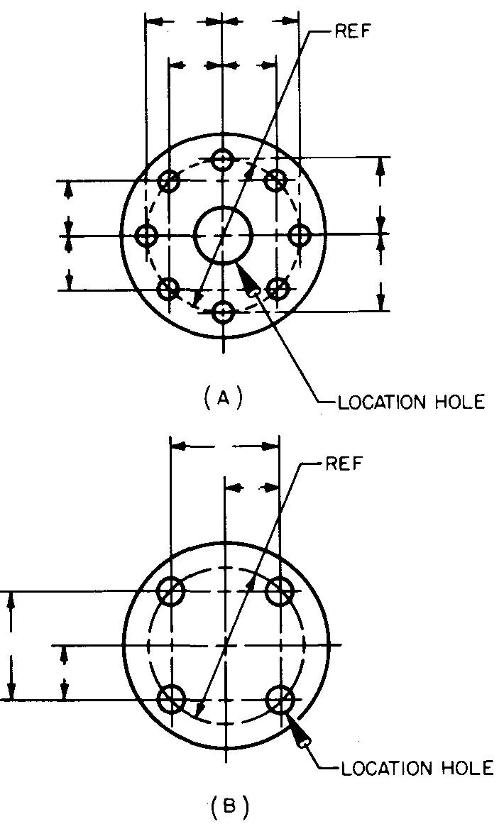
Coordinate dimensions
When one is dimensioning parts, with holes which must be accurately spaced, one hole may be selected for use as a location hole.
Dimensions are then given to all other holes horizontally from left to right and vertically above and below the location hole. All hole dimensions are given to the center lines.
These dimensions are known as coordinates. Parts with a center hole are dimensioned as in Fig. 6-18 A. Parts without a center hole are dimensioned as in Fig. 6-18B.
Fig. 6-18. Coordinate dimensions for hole spacings
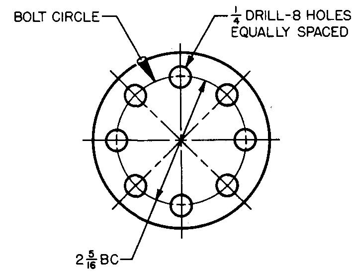
Equally spaced holes
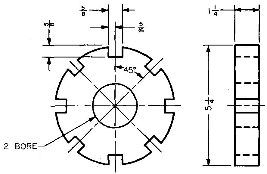
When extreme precision is not essential, the bolt-circle diameter may be given. A bolt circle is a circular center line upon which holes are spaced. A note should be given stating the hole size, the shop operation required to make the holes, and the quantity of equally spaced holes required. Many companies also include in the note the diameter of the bolt circle, followed by the abbreviation BC. The dimension may also be placed on the circular view, as shown in Fig. 6-19.
Fig. 6-19. Bolt-circle dimensions for hole spacings
Unequally spaced holes
The diameter of the bolt circle should be given, as in Fig. 6-20.
Fig. 6-20. Dimensioning unequally spaced holes
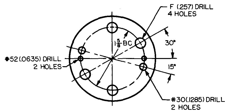
All holes, in this case, are on the same bolt circle. The center of each hole is located by the intersection of the bolt circle and a center line. The diameter and quantity of equal size holes are given in a note. The spacing of the holes around the circle is given as an angular dimension.
Dimensioning in limited spaces
When the space for a dimension is less than 3/8 inch, as in Fig. 6-21, the accepted practice is to place the arrowheads outside the extension lines.
Fig. 6-21. Dimensioning in limited spaces
Dimensioning angles
Angles are dimensioned in units of degrees (°), minutes ('), and seconds (").
Angles are usually dimensioned by placing the figures so they read from the bottom of the sheet, as shown in Figs. 6-10 and 6-11.
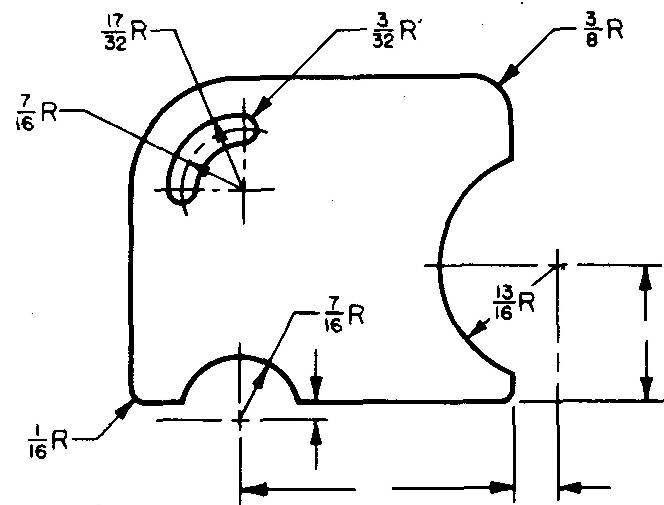
Dimensioning arcs
A circular arc is dimensioned by recording its radius. It is good practice to place the figures for radius dimensions so that they can be read from the bottom of the sheet.
If space permits, place the figure for the radius in the space along the dimension line. For radii of 3/8 inch or less, extend the dimension line for the figure outside the arc. The radius figure should always be followed by the abbreviation R.
Figure 6-22 illustrates various methods of dimensioning and locating the centers of arcs.
Fig. 6-22. Dimensioning arcs
Dimensioning parts with rounded ends
Figure 6-23 illustrates three common methods of dimensioning parts with rounded ends.
Fig. 6-23. Dimensioning parts with rounded ends
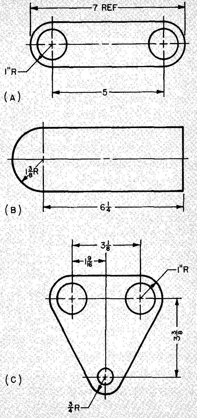
Note how the dimensions are applied in each example. Most companies omit the overall dimension or use the method shown in Fig. 6-23A.
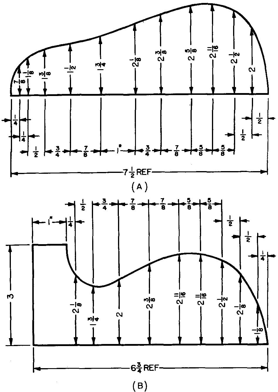
Dimensioning irregular curves
Using offsets
When large, irregular curves are dimensioned, the offset method may be used, as shown in Fig. 6-24.
Fig. 6-24. Dimensioning irregular curves using offsets
Using radii
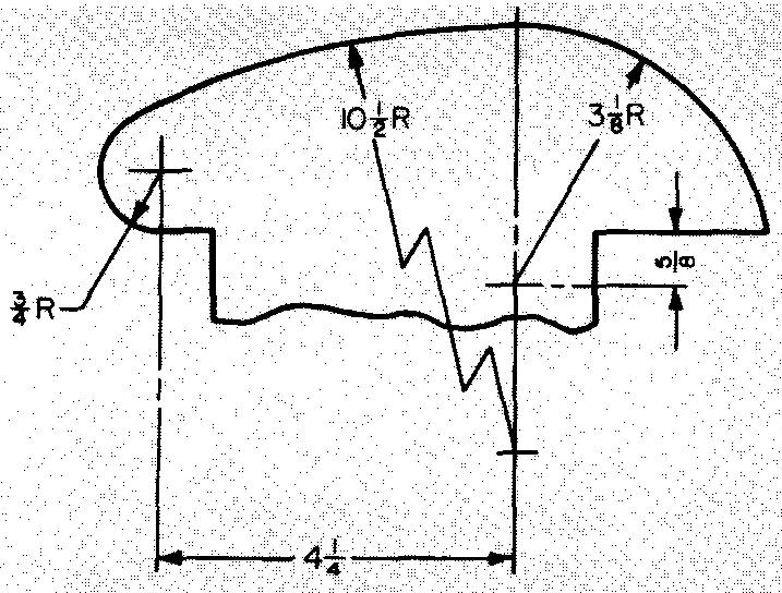
The location of the common end point of the radii for an irregular curve is often helpful in laying out the shape. The center point of a large curve frequently falls some distance away from the view.
In fact, in some cases the point may fall off the drawing sheet. The location of the center points is dimensioned as in Fig. 6-25. Note the broken line which is used to represent the large radius dimension line.
Fig. 6-25. Dimensioning irregular curves using radii
Dimensioning sectional views
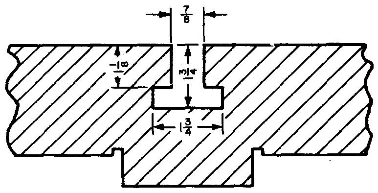
Dimensions should be placed on sectional views only when absolutely necessary. In order that dimensions will always be clearly evident, section lines are omitted around the figure, as shown in Fig. 6-26.
Fig. 6-26. Dimensioning sectional views
Dimensioning partial views
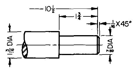
When it is necessary to dimension the length of a part which is partially drawn, only one arrowhead is used, as in Fig. 6-27.
Fig. 6-27. Dimensioning partial views
Tabular dimensioning
If several similar parts are required which differ in only a few dimensions, a table may be drawn, as in Fig. 6-28.
Fig. 6-28. Tabular dimensioning
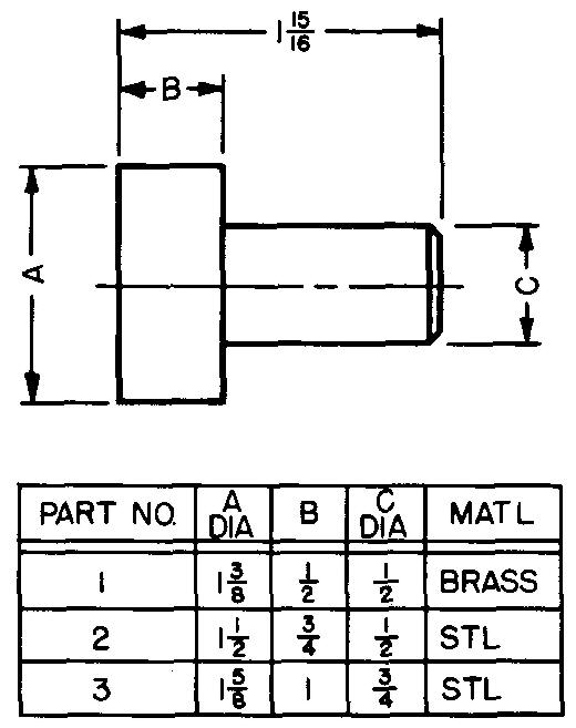
A letter is substituted on the view for each different dimension. The table lists the various letters, giving the corresponding sizes for each part number.
This method results in saving drafting time by avoiding the drawing of nearly identical parts. The size of the table may be made to suit the available space and the conditions of the part.
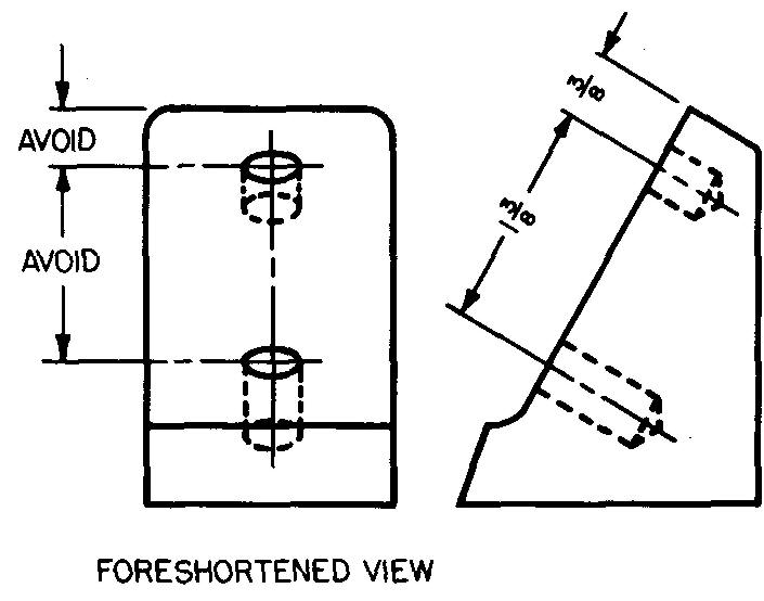
Foreshortened views
Place dimensions nearest the view which shows the true distances, as in Fig. 6-29. Avoid using foreshortened views for dimensioning.
Fig. 6-29. Dimensioning foreshortened views
Dimensioning to hidden edges
In general, avoid dimensioning features which are represented by hidden lines. In some cases, dimensions to hidden edges may eliminate the need for an extra view (Fig. 6-30).
Fig. 6-30. Dimensioning to hidden edges
Review questions (The answers are not given)
1. How far apart should dimension lines be spaced?
2. How far away should extension lines be drawn from the views?
3. How far beyond the point of the arrowhead should extension lines extend?
4. How can the draftsman reduce the number of crossings between extension and dimension lines?
5. Center lines represent the axis of precise centers of what shapes?
6. Sketch a sample center line.
7. Under what conditions is it permissible to cross the short dashes of intersecting center lines?
8. Why are arrowheads used on dimension lines?
9. Draw the two types of arrowheads.
10. How high are figures drawn? What is the total height of a fractional figure?
11. Under what conditions are feet and inch symbols used on a drawing?
12. How many times should dimensions for the same feature of a part be given?
13. Why is it considered best to place dimensions nearest the profile or contour shape of the features of the part?
14. In the aligned system of dimensioning, all figures are read from what directions?
15. In the unidirectional system of dimensioning, all figures are read from what direction?
16. Describe tie-up, duplicate, dimension.
17. What is the disadvantage of a tie-up dimension? Explain completely.
18. How does the shopman use a dimension labeled REF?
19. What is an overall dimension?
20. Why are the figures on parallel dimension lines often staggered?
21. How are base lines used?
22. How is a location hole used?
23. What abbreviation is used to tell the shopman a part is circular?
24. Sketch and apply coordinate dimensions to the circular view of a simple part similar to Fig. 6-18A.
25. How is a bolt circle used for dimensioning the location of holes?
26. What are the symbols for degrees, minutes, and seconds?
Problems: principles of dimensioning
Practice in applying the principles of dimensioning as well as the principles of notation is provided in the assignment at the end of section 7. Principles of notation.
The student should not attempt this assignment until he has studied the contents of section 7.

![]()