Principles of notation
Introduction
Notes are concisely worded statements which provide the shopman with information not otherwise shown on a drawing. Notes are always lettered horizontally on the drawing sheet.
The lettering may be drawn freehand or formed by the use of lettering guides, or templates. There is a wide choice of acceptable positions where notes may be placed upon a drawing. A good rule is to place them in as obvious a location as possible.
It is recommended that notes be lettered only after all views and dimensions have been drawn. If the draftsman forms this habit, he will be able to avoid many time-consuming erasures.
Notes may be either general notes or detail notes.
General notes consist of information which applies to the entire drawing. The information in detail notes applies only to special features of the drawing.
General notes
The draftsman may place general notes above or to the left of the sheet title block, or he may place them directly below the view of the part to which they apply.
General notes do not require the use of a leader. (Leaders and their uses are described in Sees. below)
Typical examples of general notes are listed below.
1. Finish all over (FAO).
2. Finish all over except.....
3. Fillets and rounds 1/8 R unless otherwise specified.
4. Scrape table surface only.
5. Remove all sharp corners.
6. Paint all unmachined surfaces.
7. All draft angles 5°.
8. Grind all over.
9. All diameters must be concentric within ±.001 T.I.R.
10. Remove burrs.
11. Heat-treat to Rockwell C 50-52.
12. File finish.
13. Lap 1.625 DIA hole.
14. Pickle before machining.
15. Locate holes from detail.....
16. Use pattern.....
17. Polish after plating.
18. All chamfers 1/16 x 45°.
19. Hone center hole.
20. Power brush all unfinished exterior surfaces.
21. Parts should be solvent cleaned before welding.
22. Anneal before assembly with #HF-606.
23. Tumble after removing sprue.
24. Case harden .017 deep.
25. Must be flat and free from burrs.
26. Harden and temper.
27. Normalize.
28. Make one RH as shown and one LH.
29. All bend radii 1/8 unless otherwise specified.
30. Tolerances on dimensions not otherwise specified to be ±.005.
31. All rivets 1/2 DIA unless otherwise noted.
32. Stamp (or mark) all parts with part number.
33. Pack carburize harden.
34. This part supersedes part #.....
35. Flame harden teeth only.
36. Sandblast before plating.
Detail notes
Detail notes require the use of a leader. A leader is a line which is used to connect the information in the note to the special feature of the drawing which it describes.
Positioning the note on the drawing is important. In general, notes should not be lettered on the views. There is a permissible exception to this practice. Notes may be placed in open areas on views of large parts.
This should only be done when notes placed off the views would require an unusually long leader. Good judgment is required in this case.
Notes should be spaced far enough from the views so as not to crowd but still close enough to eliminate the need for a long leader. Notes should never be lettered over any line.
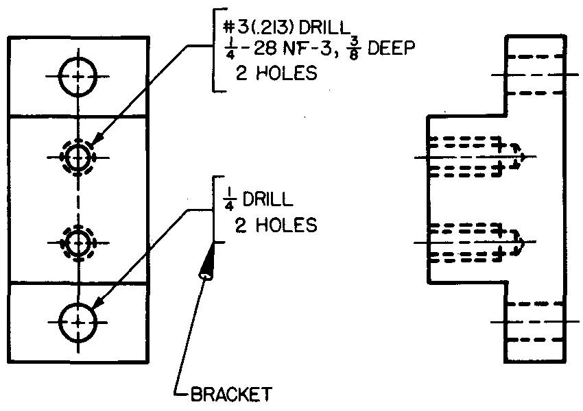
Standard practice in many industrial firms is to bracket the note, as in Fig. 7-1. Some draftsmen underline the note instead of using the bracket. Lettering for notes should always be applied horizontally on the sheet.
Fig. 7-1. Bracketed lettering
Leaders
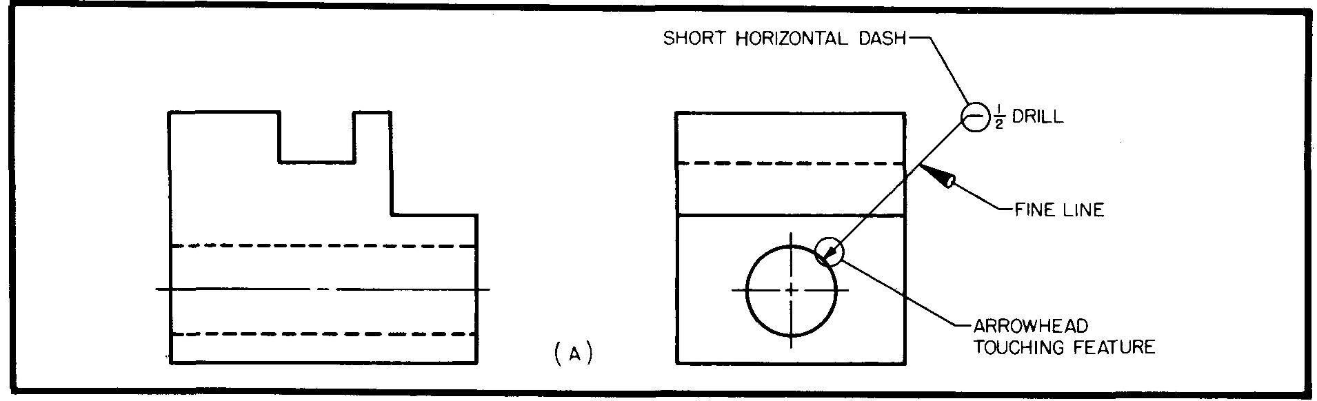
Figure 7-2 shows the principles to be considered when drawing leaders.
Fig. 7-2. How to draw leaders
Leaders are fine, straight lines. They start with a short horizontal dash from either the start or the end of the note. The other end of the leader has an arrowhead which touches the feature to be noted. Avoid using curved, horizontal, or vertical leaders.
Leaders should never be drawn parallel to object, extension, dimension, or section lines. Avoid small angles between the leader and the lines on the view. Angles of 30°, 45°, and 60° have been found best for this purpose.
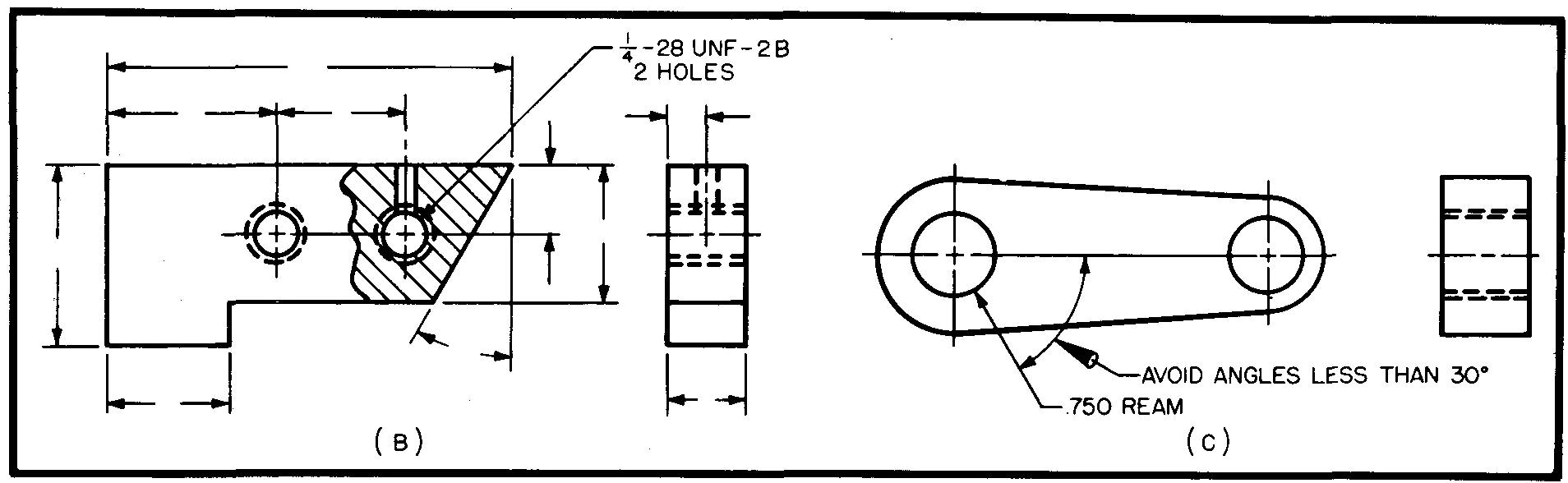
Leaders drawn to circles should be radial lines. The leader should point to the center of the circle. Avoid crossing leaders. Two or more leaders drawn to nearby features should be drawn parallel. Always draw leaders to the circular view of holes.
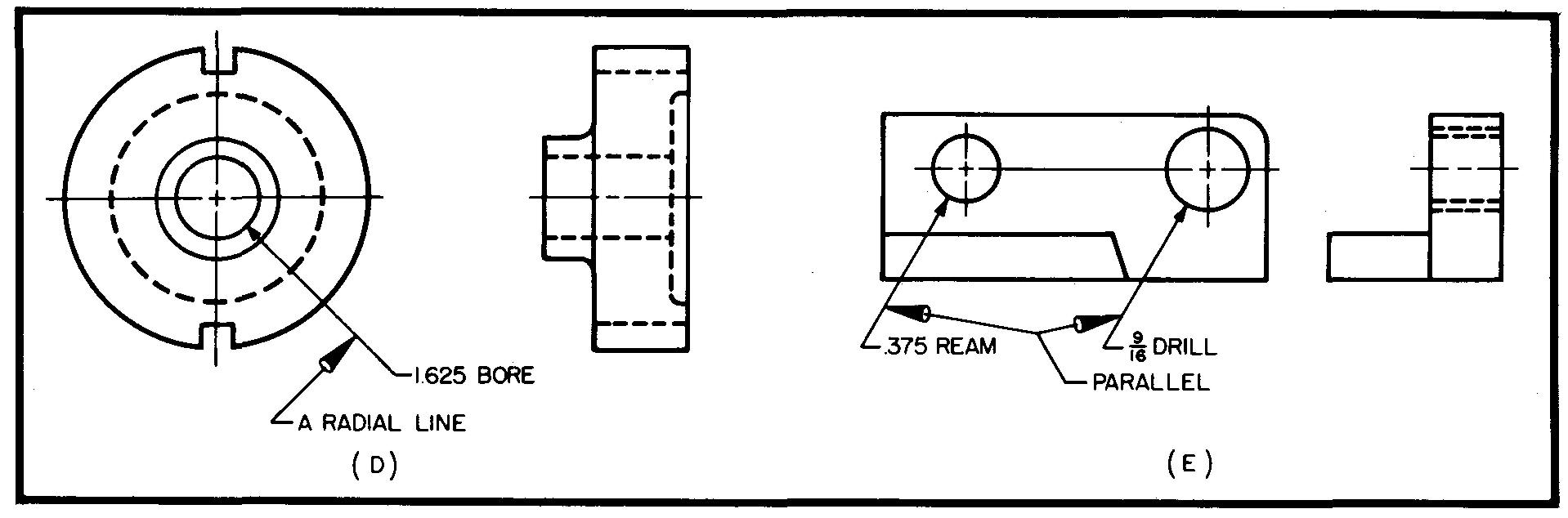
In so far as possible, leaders should be planned so the} intersect a minimum number of lines. Avoid drawing leaders through corners of the views Position notes and leaders carefully. They must be clearly evident.
Composition of notes
Ease in reading a drawing can be greatly improved by careful composition of notes Composition means the general order or arrangement of the various parts of the note, such as:
The fractional figures; the decimal figures; and the individual letters, symbols, and words. Notes should always be composed so that the various shop operations are listed in the order in which they should be performed
Practically all companies require the use on upper case letters (that is, capital letters) or. machine drawings. The letters may be in either the vertical or the inclined style of lettering.
Inclined letters should slant approximately 2 units to 5 units, as shown in Fig 6-7 (section Principles of dimensioning). Lettering 1/8 inch high is practically standard.
After deciding what information the note should contain, the draftsman should next plan the length of the lines of the note.
Except in special cases, the lines should contain an average of about five words a line.
Two or more lines which do not contain fractions may be spaced as close as one-hall: a letter height, or 1/16 inch, as shown in Fig. 7-3.
Fig. 7-3. Line spacing without fractions
Lines which contain fractions should be spaced from 1 to 1-1/2 times the letter height, as shown in Fig. 7-4.
Fig. 7-4. Line spacing with fractions
The wider line spacing is required in this case because the fractions, being 5/16 inch high, require more space than the standard 1/8-inch lettering.
A note which consists of more than one line must be carefully planned. The length of the lines should be neatly balanced whenever possible.
A neatly balanced note is one in which a rectangular effect has been created, as seen in Fig. 7-5.
Fig. 7-5. Balancing notes
This is done by spacing the words in the note so that both ends appear approximately even.
Balance is not always possible because of the wording of the note. In Fig. 7-4, for example, a single line would be too long; and the two lines cannot be equal in length. It is possible in this case to line up only the left side of the note.
In some notes of two or more lines containing fractions, a problem may be created by the alignment of the fractions, one over the other. To prevent possible confusion, it is customary to indent every other line in notes of this type, as shown in Fig. 7-6.
Fig. 7-6. Indenting alternate lines
Words or groups of words which suggest separate ideas should be separated with a dash or a comma, shown also in Fig. 7-6. The draftsman should use the standard abbreviations as listed in Table 1.
Recommended notation
Methods of producing and specifying hole sizes on detail drawings are often given in a note. Most companies arrange the note so the hole diameter is followed by the word indicating the shop operation, such as drill, ream, or bore. This practice of stating the shop operations for producing holes is not always followed.
Among notable exceptions are machine drawings made to military standards and machine drawings for various large electronic equipment manufacturers.
When a hole is identical in size to other holes on a part, a leader is drawn to the most convenient or the most prominent hole on the part. The note should specify the number of identical holes required.
Thus it is necessary to draw a leader to only one hole which is typical of the others.
Figure 7-7 shows two views each of countersunk, counterbored, and spotfaced holes. (These processes are described in Sees. 12.6 through 12.8. section Basic machining operations)
Fig. 7-7. Arrowhead interference
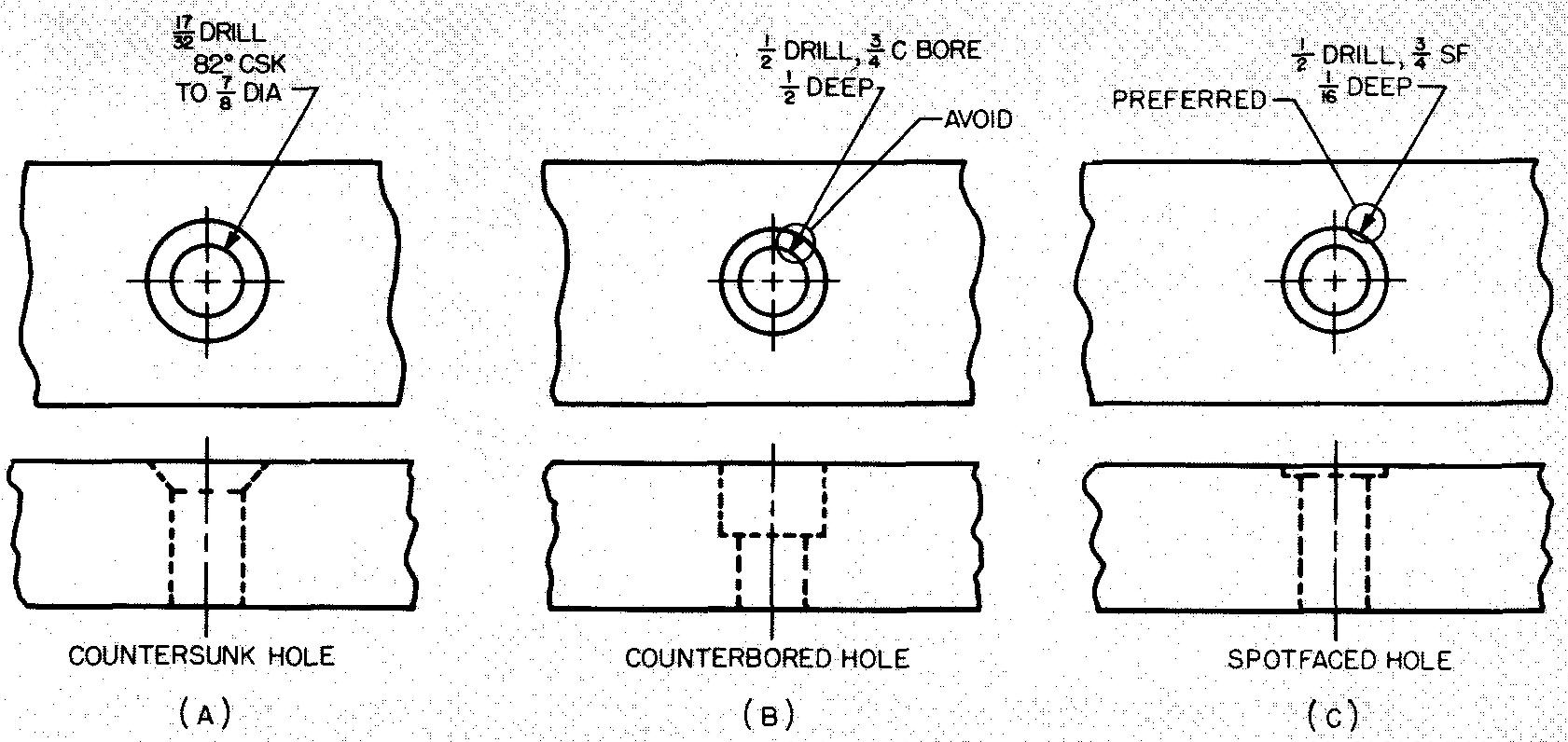
These holes are represented as concentric circles in the circular view. (Concentric is denned as two or more circles drawn from the same center.) In most drawings the arrowhead on the leader should touch the inner circle which, in each case, is the first hole the shopman will make.
However, for some holes, if the arrowhead is drawn to the inner circle, it may interfere with the outer circle, as shown in Fig. 7-7B. In this case, it is better to draw the arrowhead to the outer circle, as shown in Fig. 7-7C.
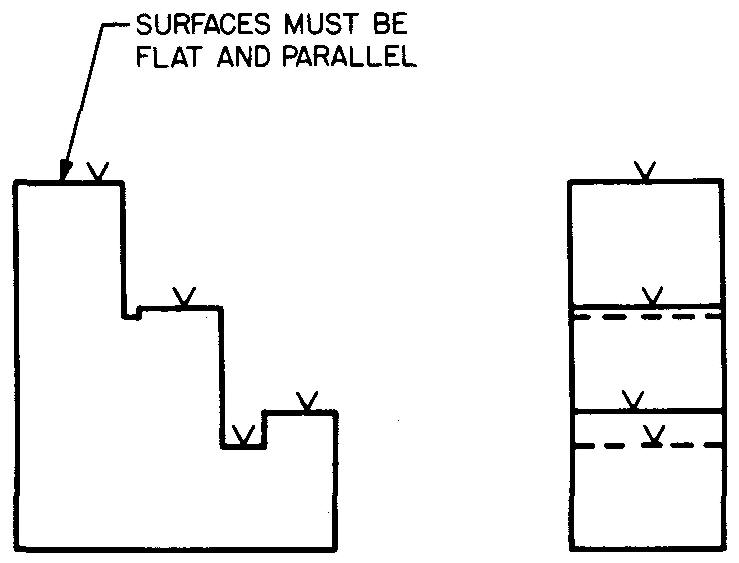
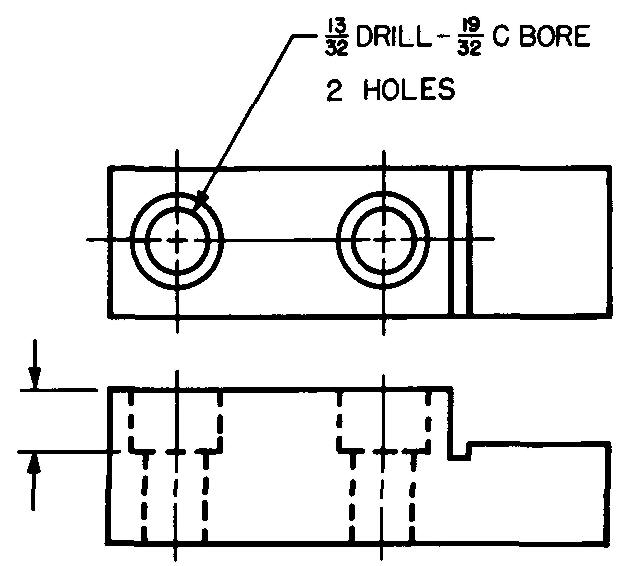
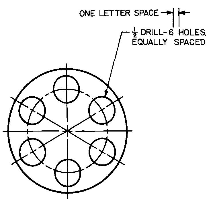
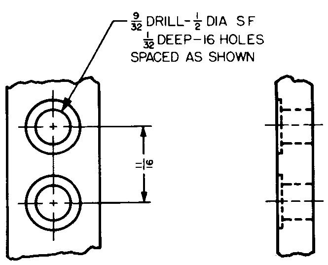
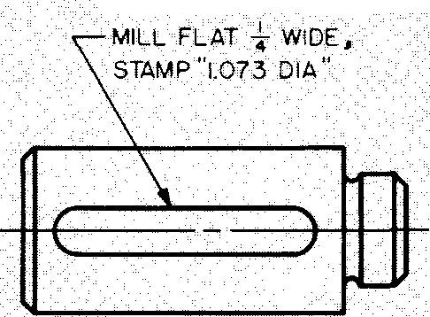
Figures 7-8 through 7-16 illustrate other common examples of detail notes and miscellaneous notations for machine parts.
Fig. 7-8. Miscellaneous notation
Fig. 7-9. Miscellaneous notation
Fig. 7-10. Miscellaneous notation
Fig. 7-11. Miscellaneous notation
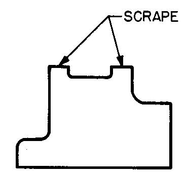
Fig. 7-12. Miscellaneous notation
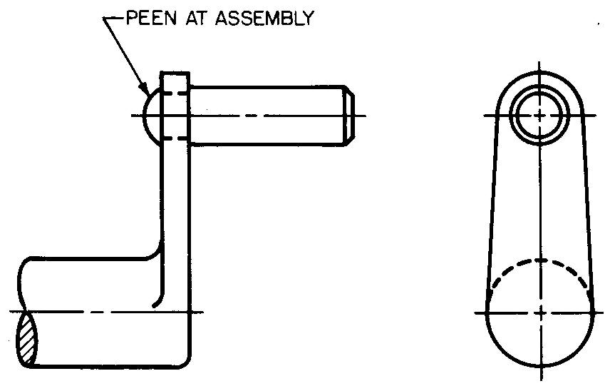
Fig. 7-13. Miscellaneous notation
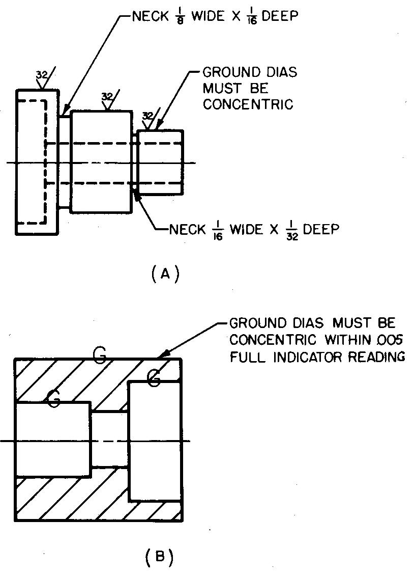
Fig. 7-14. Miscellaneous notation
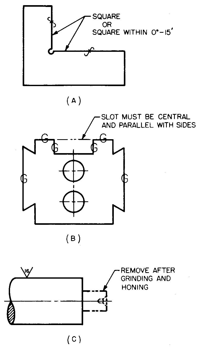
Fig. 7-15. Miscellaneous notation
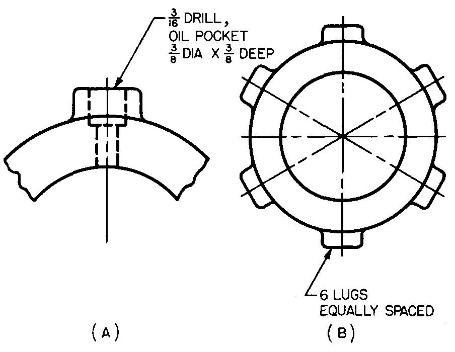
Fig. 7-16. Miscellaneous notation
Review questions (The answers are not given)
1. Define the term notes.
2. Why should the notes be lettered on the drawing only after all the views have been drawn and the dimensions have been added?
3. List and describe the two kinds of notes.
4. Describe the use of a leader.
5. Why is it recommended that notes be placed off the views?
6. What is meant by the composition of a note?
7. What is the standard height of lettering for industrial drawings?
8. After carefully reading Sec. composition of notes, letter the following notes:
1) Drill and ream for #2 taper pin.
2) 9/32 drill, 13/32 DIA counterbore, 1/4 deep, 5 holes.
3) 15/16 drill, 2 holes in line.
Problems: principles of dimensioning and principles of notation
Using the freehand sketches prepared for the problems in section Principles of detail drawings and Conventional representation, apply the necessary dimensions and notes to the views so as to complete the drawings.

![]()