Principles of sectional views
Introduction
Sectional views should be drawn when the interior features of parts cannot be clearly understood from the usual orthographic views.
A sectional view is made as if on that view the nearest part of the object were cut or broken away. Sectional views are used extensively on machine drawings.
The cutting plane
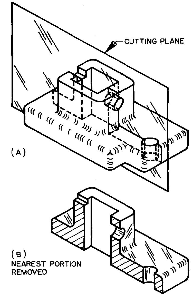
The position of the imaginary cut is shown by the cutting plane, pictured in Fig. 4-1.
Fig. 4-1. The cutting plane
It always appears on the drawing as an edge. The edge view of a plane is represented by a line. The line showing the cut is therefore known as a cutting plane line.
The cutting plane line
The heaviest line used on a drawing, as shown in Fig. 4-2, is the cutting plane line.
Fig. 4-2. The cutting plane line
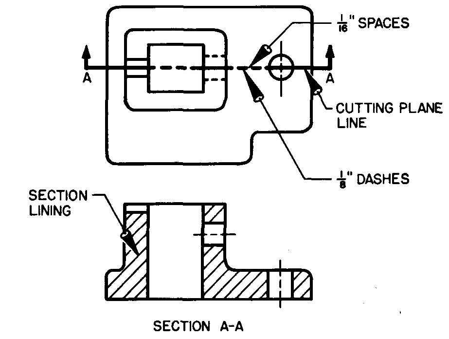
It is a bold line made up of a series of one long and two short dash lines. It is used in place of any other line which may appear in the same position on the view.
The cutting plane line does two things:
1. It shows exactly where the object is cut.
2. It shows the direction of the line of sight relative to the cut portion of the object.
Line of sight means the direction from which the observer views, or looks at, an object. Bold line-of-sight arrowheads are usually drawn at the ends of the cutting plane line, as shown in Fig. 4-2.
Capital letters such as A-A and B-B are placed at each end of the cutting plane line.
Both the letters and the arrowheads indicate the direction of sight for viewing the section. A note (Section A-A, B-B, and so on) is placed under the corresponding sectional view, as in Fig. 4-2.
The cutting plane line, the arrowheads, and the identification letters may be omitted for sections which cut through the major center line of a part or for sections where the cut on the part is evident.
Section lining
Lines used to indicate the surfaces where the imaginary cutting plane cuts the material, Fig. 4-2, are called section lining or cross hatching.
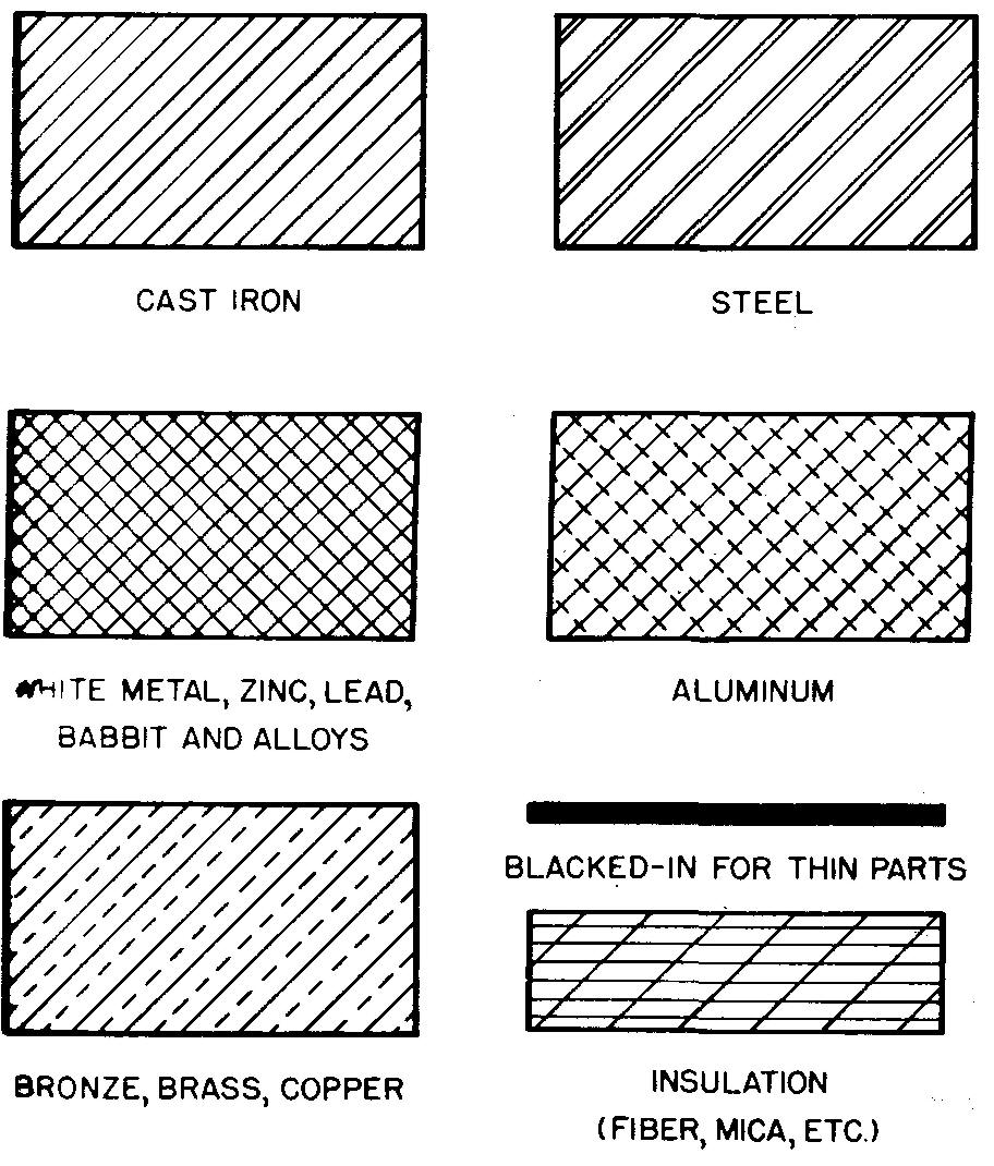
Section lining is represented by thin lines, spaced evenly by eye. Several kinds of symbolic section lining for various materials are shown in Fig. 4-3.
Fig. 4-3. Symbolic section lining
Section lining in detail drawings
Cast-iron section lining is used for detail drawings in practically all cases, regardless of the material of the part, as shown in Fig. 4-4.
Fig. 4-4. Section lining on detail drawings
The kind of material should be given, preferably in the title under the view of the part, as in Fig. 3-10 (section Principles of detail drawings), or, in some cases, in the parts list on the assembly drawing, as in Fig. 17-9 (section Principles of assembly drawings).
Cast-iron section lining is drawn at a 45° angle. The lines are uniformly spaced. Generally these lines are from 1/16 to 1/8 inch apart.
Wider spacing may sometimes be used for larger areas. The width of the spacing depends upon the size of the area to be sectioned.
Section lining in assembly drawings
Cast-iron section lining is used for detail drawings in practically all cases, regardless of the material of the part, as shown in Fig. 4-4.
The kind of material should be given, preferably in the title under the view of the part, as in Fig. 3-10, or, in some cases, in the parts list on the assembly drawing, as in Fig. 17-9.
Cast-iron section lining is drawn at a 45° angle. The lines are uniformly spaced. Generally these lines are from 1/16 to 1/8 inch apart. Wider spacing may sometimes be used for larger areas. The width of the spacing depends upon the size of the area to be sectioned.
Section lining in assembly drawings
On assembly drawings, symbolic section lining (shown in Fig. 4-3) is used to identify parts made of different materials. (See section Principles of assembly drawings)
For any two parts which are next to each other, the section lining should be drawn in a different direction for each part. Where a third part touches both of the other two parts, the section lining should be drawn at a different angle to the others, as in Fig. 4-5.
Fig. 4-5. Section lining on assembly drawings
If the shape or the position of the part causes 30°, 45°, or 60° section lining to be parallel, or nearly parallel, to a nearby line of the part, another angle should be chosen, as in Fig. 4-5 at A.
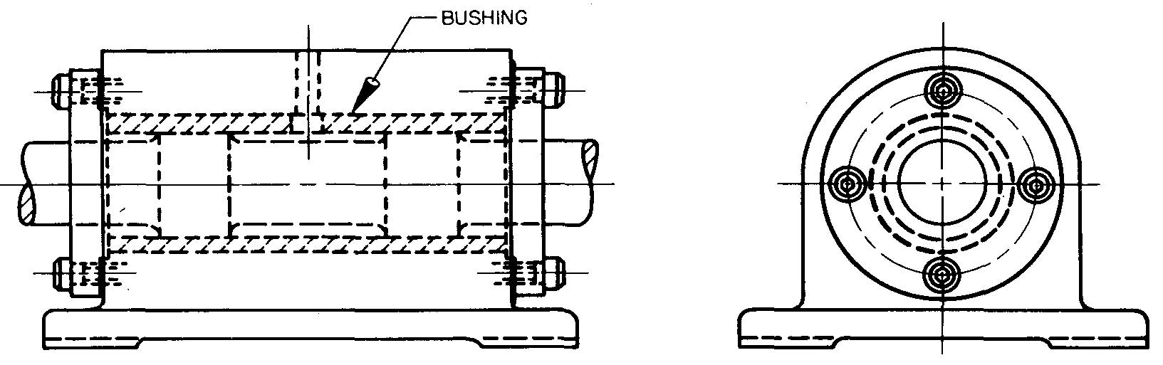
Hidden lines in sectional views
Sectional views should clearly represent features of parts which might be confusing if drawn on the usual orthographic views.
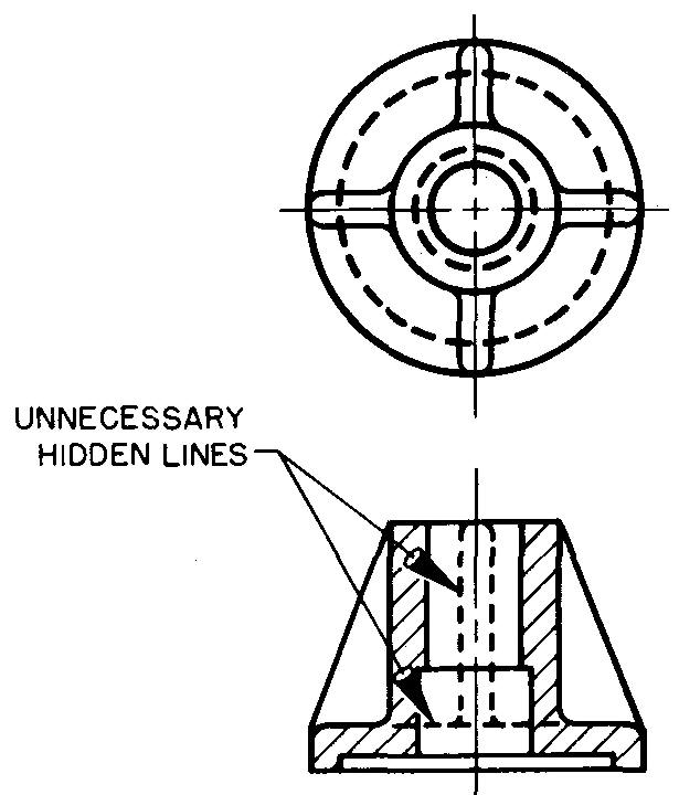
When hidden lines are drawn, the sectional views often become difficult to read. In these cases hidden features behind the cutting plane should often be omitted entirely.
A sectional view with unnecessary hidden lines is shown in Fig. 4-6.
Fig. 4-6. Unnecessary hidden lines
In some cases, however, a few hidden lines must be shown so that all the features of the part may be understood. Sometimes hidden lines may be shown to eliminate the need for an extra view, as in Fig. 4-7.
Fig. 4-7. Necessary hidden lines
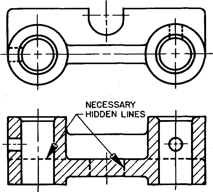
The draftsman must use careful judgment in determining whether to show hidden lines. A thorough examination of the part should be made to determine if hidden lines on the sectional view are absolutely essential.
Principal kinds of sectional views
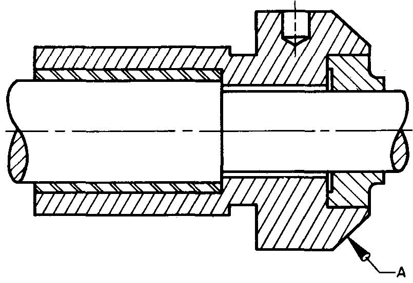
Full sections
Figure 4-8A shows how a full section is obtained when the cutting plane line extends entirely through the object.
Fig. 4-8. Full sections
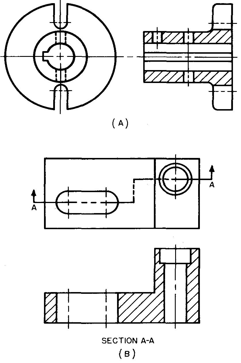
The line usually extends along the major center line, although its direction may be changed to cut through some feature not lying on the center line, as in Fig. 4-8B.
In Fig. 4-8A the cutting plane line is not shown because the location of the cutting plane is obvious.
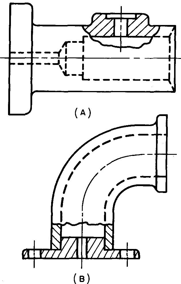
Half sections
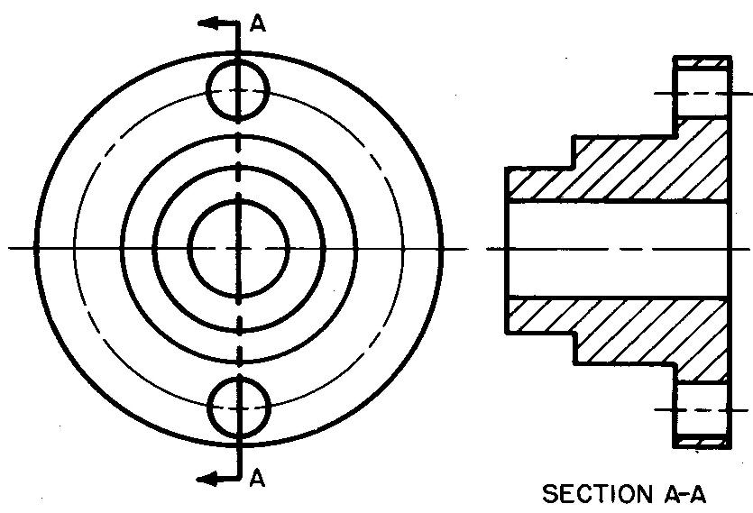
When the cutting plane line extends half way through the object, as in Fig. 4-9, the resulting view is called a half section.
Fig. 4-9. Half sections
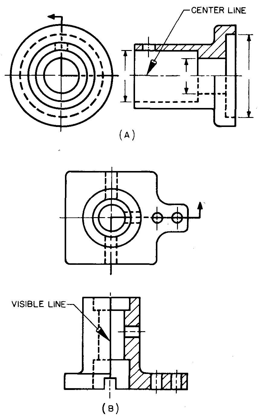
In this sectional view the part is drawn as if one-quarter of the object were removed. Half of the interior is thus exposed to view. Hidden features may be drawn in the unsectioned half if necessary for dimensioning purposes, as in Fig. 4-9A.
Half sections show the external as well as the internal features of a part. Sectional views of this kind are usually used when the part is symmetrical, or balanced about the center line.
Either a center line (preferred), Fig. 4-9A, or a visible line, Fig. 4-9B, may be used to separate the sectioned half from the uncut half.
Offset sections
In Fig. 4-8B and in Fig. 4-10 the cutting plane line does not cut the view along one continuous center line. Its direction is offset, or bent, to include features of the part which do not lie along a continuous straight line.
Fig. 4-10. Offset sections
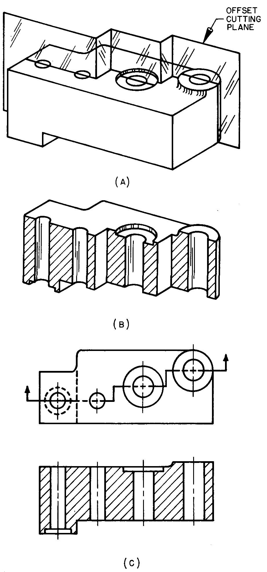
The offset section is especially useful for showing the interior construction of parts which have irregularly spaced holes, cuts, spokes, and other features.
Notice that in Fig. 4-10C the section lining is drawn as if the cutting plane extended continuously along a straight line. The offsets are not shown in the sectional view.
Revolved sections
Figure 4-11 illustrates a revolved section which is drawn when the true shape of a particular feature of a part would not be clearly shown by the usual orthographic views.
Fig. 4-11. Revolved sections
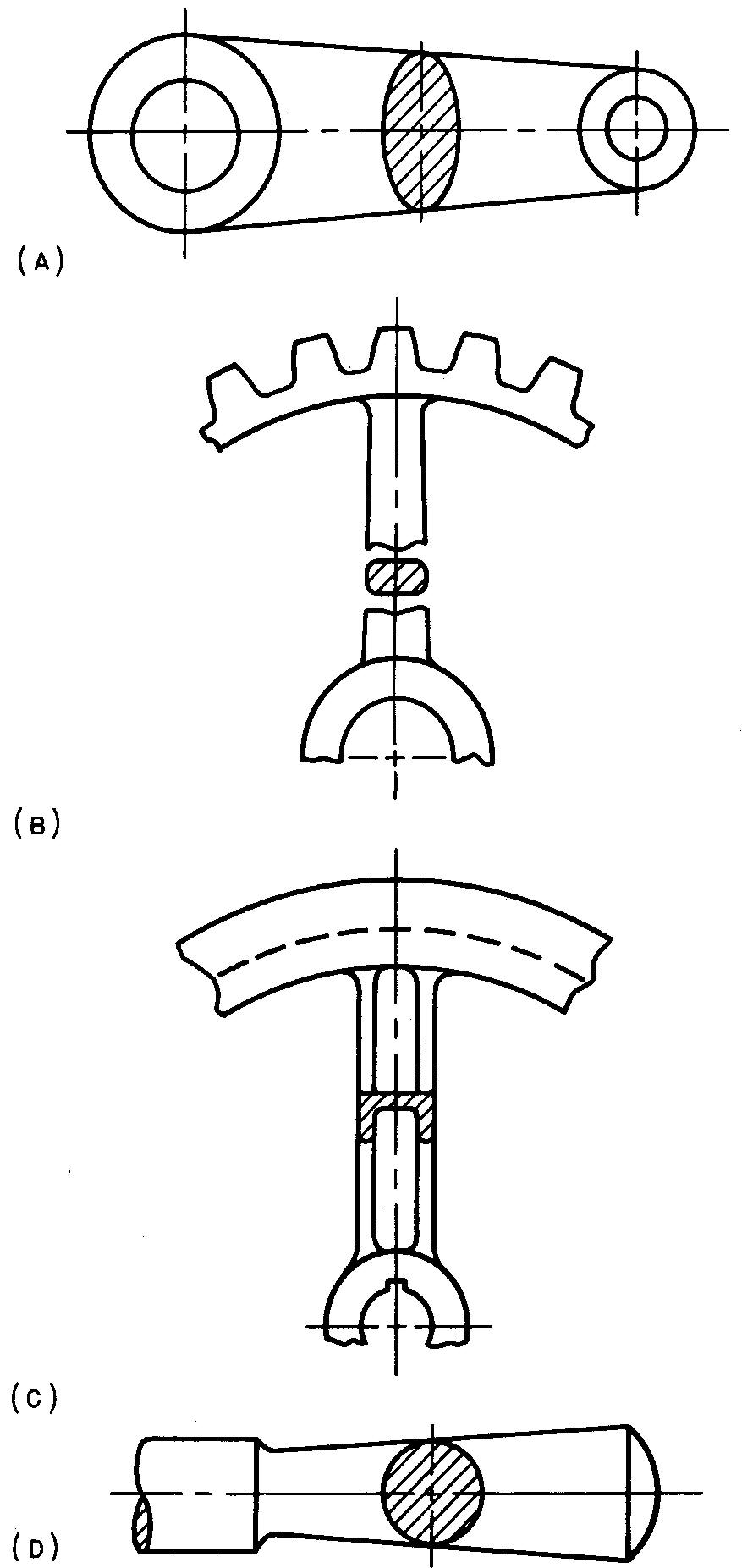
The sectional view is obtained by assuming a cutting plane perpendicular to the axis of the feature to be shown. The portion thus cut is revolved about a center line through 90° into the plane of the paper.
Break lines may be used on each side of the section, as in Fig. 4-11B.
All original lines which would normally appear but are covered by the revolved section are removed, as in Fig. 4-11C.
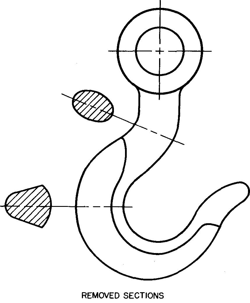
Removed, or detail, sections
Full, revolved, or partial sections may be removed from their usual positions on the view and drawn elsewhere on the drawing sheet. Removed sections are frequently drawn to an enlarged scale to emphasize certain features of a part.
Removed sections may be placed in any convenient position on the sheet. The use of identification letters, such as section A-A, is recommended in cases where the sectional view might be confusing.
Note the use of a center line to represent the cutting plane line in Fig. 4-12.
Fig. 4-12. Removed, or detail, sections (ASA Y 14.2-1957)
Broken-out, or partial, sections
Figure 4-13 illustrates partial sections, which are used when only certain features in a view of a part require further clarification or emphasis.
Fig. 4-13. Broken-out, or partial, sections
In this case, only those particular features are sectioned. A break line is used to separate the sectioned area from the remaining portion of the view.
Thus, by showing only a partial section of an entire view, the need for drawing a full or half section is eliminated. Broken-out sections may be removed from the view in special cases.
Thin sections
This type of sectional view, Fig. 4-14, is used mainly on sheet-metal and on structural drawings.
Fig. 4-14. Thin sections
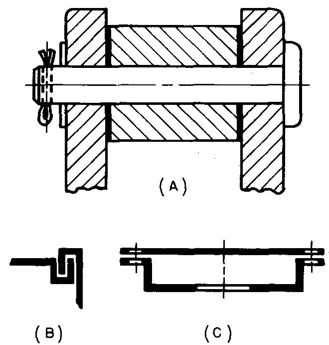
It represents thin parts such as gaskets and packing. Because of the small wall thickness of the parts, section lines are usually not drawn. Thin features of two or more adjacent parts are blacked-in, with spaces shown between each piece, as in Fig. 4-14B and C.
Phantom sections
When a draftsman wishes to show both the interior and exterior features of a part on the same view on assembly drawings, he often uses a phantom section.
The section lining is represented by thin broken lines. The chief use of phantom sections is in cases where a broken-out section would prevent the exterior features from being shown.
Phantom sections are shown in Fig. 4-15.
Fig. 4-15. Phantom section
Review questions (The answers are not given)
1. What is the main purpose of sectional views?
2. Describe the use of the cutting plane in sectional views.
3. Draw a sample cutting plane line.
4. How does the cutting plane line aid the shopman to understand the sectional view?
5. What is meant by line of sight!
6. What is the purpose of letters A-A, B-B, and so on, which are placed at the ends of the cutting plane line?
7. Describe the purpose of section lining.
8. What type of section lining symbol is usually used on detail drawings, regardless of the materials to be used in the construction of the part?
9. For any two parts which are next to each other, section lining should be drawn in what directions?
10. What are the most common angles for drawing section lining?
11. Under what conditions may hidden lines be shown on sectional views?
Problems: principles of sectional views
Problems in sectional views will be found at the end of section Conventional representation. The student should not attempt these problems until he has studied the contents of section Conventional representation.

![]()