Principles of tolerancing
Introduction
Moving parts of machines and structures must be made to a precise size so that, when assembled, they will fit and work together properly. Parts for machines which are produced in great quantities must be interchangeable.
For example, if a sewing machine develops a worn or broken part, the machine will not work until the worn part is replaced by a new part.
If the new part is interchangeable, it may be picked from stock and fit into place, functioning properly without special tooling. Interchangeability requires that all like parts be made to a nearly identical size.
As long ago as 1785, Thomas Jefferson, then Minister to France, wrote in describing the manufacture of guns, ". . . it consists of making every part of them so exactly alike that what belongs to one may be used for any other."
Eli Whitney is said to be the first to introduce interchangeability of parts in America. In 1798 he obtained a government contract for the manufacture of firearms in New Haven, Connecticut.
Interchangeable parts are the foundation of modern manufacture.
For example, in the early stages of automobile manufacture the few automobiles that were completed were far too costly for the average man. During these stages, parts for an automobile were made, one by one, by painstaking hand methods.
Today, automobile parts made by machine tools are so accurately produced that assembly into a finished product is an easy, fast, and economical process.
The result is that, instead of being able to make only a limited number of automobiles at great expense, the manufacturer can now build them in vast quantities.
The large volume of production is achieved at a reasonable cost so that automobiles are brought within the reach of practically everyone.
Because of accurate machine tools, the quality of workmanship which makes interchangeability possible is as easily available to a plant employing only a few workers as it is to a plant employing thousands of workers.
Because of interchangeability, the benefits of mass production are available to all.
As a consequence, the standard of living in the United States has been raised so that today it is one of the highest standards of living in the world.
Things that once were regarded as expensive luxuries are now considered comparatively cheap necessities in our country; yet they remain expensive luxuries to people in those parts of the world where mechanization and mass production are relatively untried.
The automobile is, of course, the most familiar example of modern mass production. But there are many other products which could be cited, such as home appliances, business machines for the office, military items, or agricultural machinery for the farm.
The economy of mass production has made thousands of products available to everyone at a moderate cost. It has also provided jobs for millions of workers in the cities, towns, and countryside.
These same workers would undoubtedly be unemployed today if the production methods of a half century ago had not been changed to modern production methods. Modern industry does have some limitations. It cannot economically make machine parts consistently to an identical size.
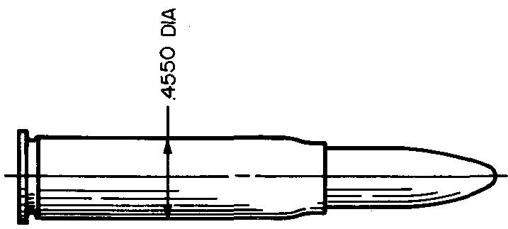
In Fig. 11-1, for example, a diameter of the bullet cartridge is dimensioned as 0.4550 inch. While it is perhaps possible to make a limited number of cartridges to this exact size, the production would be extremely slow.
Fig. 11-1

Considerable spoilage might occur because of the exact size requirement. Parts with exact dimensions are practically impossible to produce.
Because of the way it is dimensioned, if the shopman made the cartridge as much as 0.0001 inch undersize, the cartridge would not be acceptable.
Consider how expensive it would be to buy a present-day automobile if all the parts were dimensioned in this way. It is doubtful if there would be enough automobiles made in any one year to meet the demand. Production would be limited once again almost to a handmade basis.
Tolerancing
Slight variations are allowed in dimensions.
However, dimension variations must be restricted to a minimum to enable parts to function effectively. This is called tolerancing.
Thus the shopman is permitted a small margin of error. In Fig. 11-2, a diameter of the cartridge is dimensioned as 0.4555/0.4545 inch.
Fig. 11-2
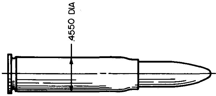
The cartridge may now be made as large as 0.4555 inch, as small as 0.4545 inch, or any size in between the two figures. The restricted amount of variation works out to be 0.0010 inch.
The amount of variation, or
tolerance, is found by taking the difference between the two numbers.
Tolerancing can save considerable time, effort, and, of course, ultimate
expense.
Terms used in tolerancing
A standard procedure which specifies allowable differences or variations in size for two mating parts has been devised. In the explanation of this procedure, certain new terms will be used. The student should study these terms so that he can understand them.
Nominal size
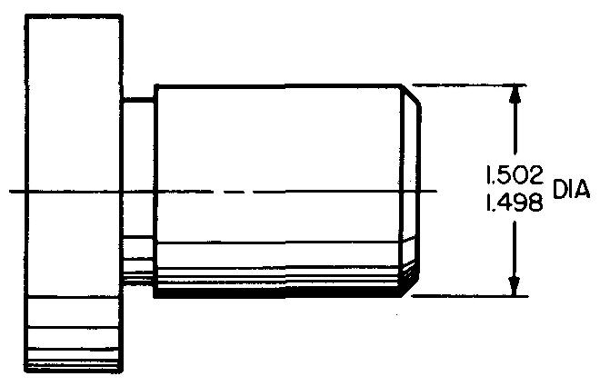
The approximate size of a part is called its nominal size. Nominal size is usually written in fractional form. The nominal size for the diameter of the part shown in Fig. 11-3 is 1-1/2 inches. That is, both dimension figures are closest to 1-1/2 inches.
Fig. 11-3
Basic size
The exact theoretical size of a part is its basic size.
The basic size is used as a starting point for working out the two figures that are placed on the drawing. The basic size is usually the decimal equivalent of the nominal size.
For the part in Fig. 11-3 the basic size is 1.500 inches. (1-1/2 in. = 1.500 in.)
Limits
The largest and smallest acceptable sizes of a dimension for a part are the limits of the dimension. In Fig. 11-3 the largest limit is 1.502 inches and the smallest limit is 1.498 inches.
Tolerance
The difference found by subtracting the smallest limit from the largest limit is the tolerance. This is the total amount of variation which can be permitted and still produce a properly functioning part.
In Fig. 11-3 the tolerance is 0.004 inch. (1.502 in. - 1.498 in. = 0.004 in.)
Allowance
The tightest fit between two mating parts is called the allowance. There are two kinds of allowance: interference allowance and clearance allowance.
Interference allowance
As the word suggests, interference refers to the amount one part interferes with its mating part. Interference always indicates that the parts will fit tightly together. Figure 11-4 shows a shaft and a hole which are designed to fit together.
Fig. 11-4. interference fit for mating parts
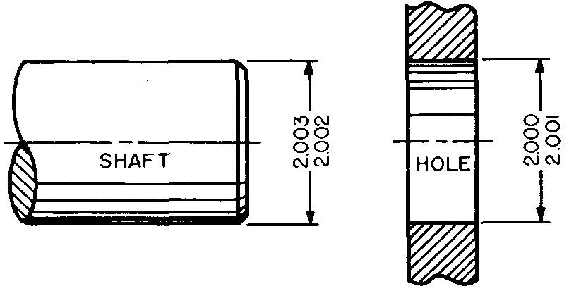
They are dimensioned for an
interference fit; that is, the hole is smaller than the shaft so the parts will
fit tightly together.
Let us examine the dimensions of each of these parts.
To calculate the greatest amount of interference between two mating parts, we must subtract the smallest hole diameter (2.000 inches) from the largest shaft diameter (2.003 inches). This will give a maximum interference of 0.003 inch. This means that the shaft must be forced into the hole.
Clearance allowance.
Clearance, as the word implies, means the amount one part clears or is smaller than its mating part. Clearance always means that the parts will fit loosely together.
Figure 11-5 shows another shaft and hole which are designed to fit together. The hole is identical in size to the hole in Fig. 11-4 but the shaft diameter is different. This pair of mating parts is dimensioned for a clearance fit.
Fig. 11-5. clearance fit for mating parts
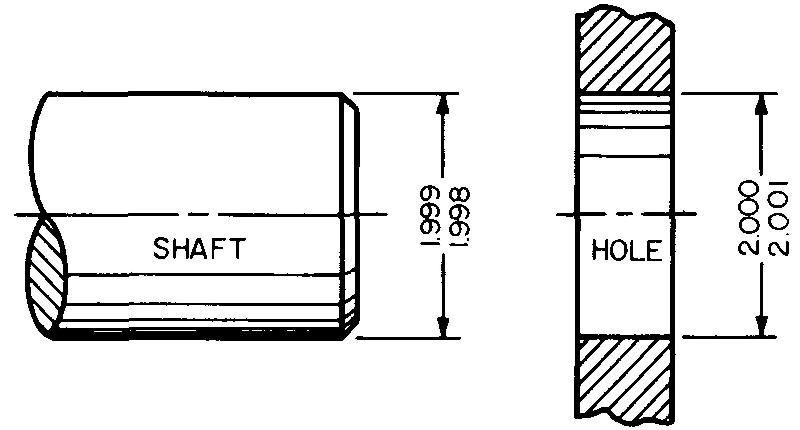
To calculate the smallest amount of clearance between these two mating parts, we must subtract the largest shaft diameter (1.999 inches) from the smallest hole diameter (2.000 inches). This tells us the shaft will slip loosely into the hole, giving a clearance of 0.001 inch.
Remember, both the largest interference and the smallest clearance refer to allowance in tolerancing. Notice in both examples we used the smallest hole size and the largest shaft size to find the allowance.
Applying tolerances
When we apply a tolerance, we select the figures for the parts so that the dimensions may be placed on the drawing. There are two systems for applying tolerances: the basic hole system and the basic shaft system.
We will discuss the basic hole system in this text since it is the more commonly used system.
The hole or slot in a machine part is made by using a standard size tool or cutter which performs the operation within certain predictable limitations (see Table 5 Machining tolerances).
From the design layout or from the assembly drawing, the draftsman determines the nominal size for the hole or slot for which the tolerance is to be applied.
The designer may prefer to indicate this size on his layout or the draftsman may simply scale (or measure) the designer's drawing to determine the nominal size of the hole.
The shaft or other mating part may be easily made to a suitable size to fit the hole or slot. In the basic hole system, the smallest limit for the hole or slot is always used as the basic size.
This is the starting point from which all calculations are made. Thus the term basic hole for this method.
Let us closely examine two examples showing how a machine draftsman applies a tolerance in order to correctly dimension each of two mating parts.
Example 1 key and slot
We shall take for our first example two mating parts which have a key and slot as shown in Fig. 11-6. In Fig.
Fig. 11-6. Clearance fit for mating parts

11-6A the dimensions have been intentionally omitted from the views. The final dimensions, shown in Fig. 11-6B, were obtained in the following manner.
First the draftsman must determine the nominal size of the slot from the design drawing. In this case it is 3/4 inch. Thus the basic size is 0.750 inch. (3/4 in. = 0.750 in.)
Before the draftsman can apply a tolerance to either part, he must know how the mating parts are expected to work. For this example, the key must slide in the slot with a clearance allowance of 0.001 inch.
The amount of tolerance to specify in each case requires a thorough knowledge of how accurately the shopman and the machines can make parts to size.
Here a beginning draftsman would do well to seek the advice of experienced draftsmen or engineers.
In this case the draftsman is advised to make each tolerance 0.001 inch.
The draftsman now knows four sizes: the nominal size, the basic size, the allowance (in this case, clearance allowance), and the tolerance for both the key and the slot.
Solution
KNOWN DATA:
Nominal Size 3/4 in.
Basic Size 0.750 in.
Allowance (Clearance) 0.001 in.
Tolerance (Slot and Key) 0.001 in.
REQUIRED:
Slot Limits 7
Key Limits 7
STEP 1:
The basic size is always the smallest slot or hole size. Begin by adding the tolerance to the basic size. This gives the largest slot limit.
Basic Size (Smallest Slot Limit) 0.750 in. Tolerance 0.001 in.
Largest Slot Limit 0.751 in.
STEP 2: From the KNOWN DATA select the allowance.
Since this is a clearance allowance, the key must be smaller than the slot. Subtract this clearance allowance from the basic size to find the maximum key limit.
Basic Size (Smallest Slot Limit) 0.750 in.
Allowance 0.001 in.
Largest Key Limit 0.749 in.
STEP 3: From the KNOWN DATA select the tolerance for the key. Subtract this from the largest key limit to find the smallest key limit.
Largest Key Limit 0.749 in.
Tolerance 0.001 in.
Smallest Key Limit 0.748 in.
STEP 4: CHECK.
By definition, the difference between the smallest slot limit and the largest key limit equals the allowance.
Subtract and compare the difference with the allowance stated in KNOWN DATA.
Smallest Slot Limit 0.750 in.
Largest Key Limit 0.749 in.
Allowance 0.001 in.
Example 2 shaft and hole
Now let us study another example, shown in Fig. 11-7.
Fig. 11-7. Interference fit for mating parts
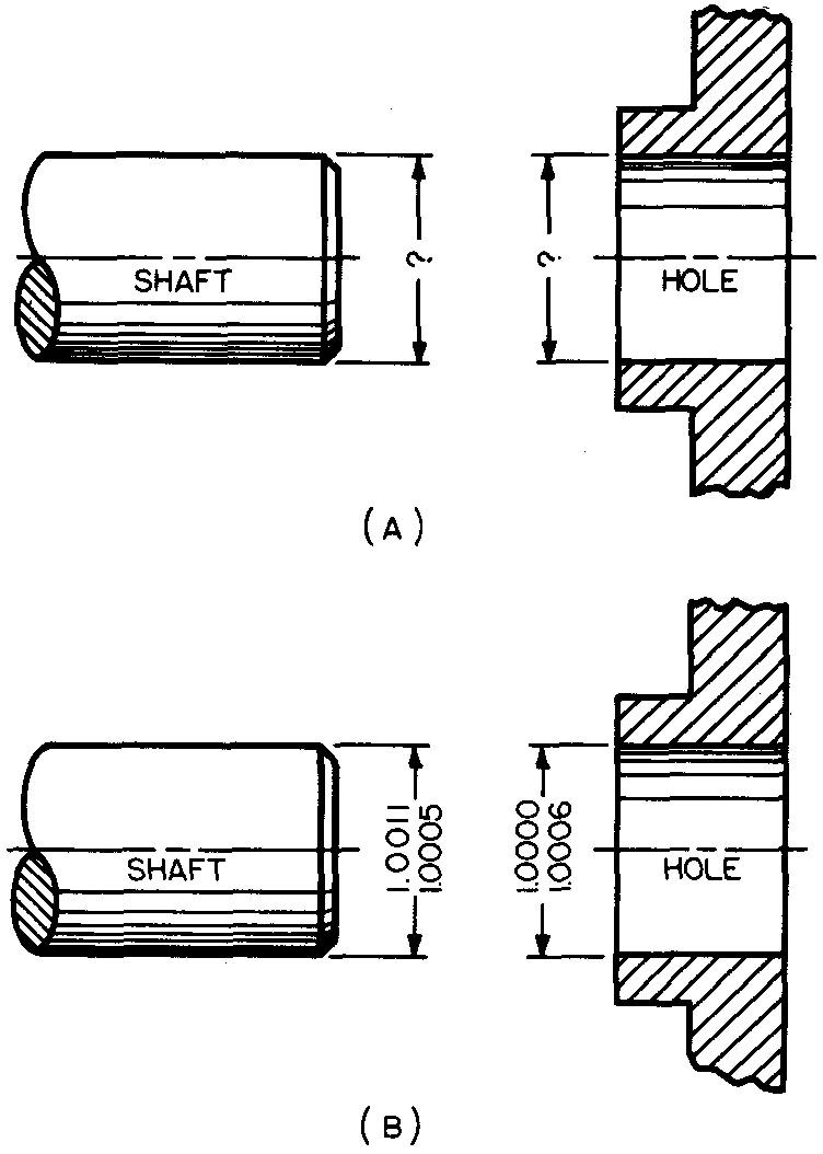
Again the dimensions have been omitted from the views in Fig. 11-7A.
The final dimensions, applied in Fig. 11-7B are explained as follows.
As in Example 1, the draftsman starts with the hole size. He finds it to measure 1 inch diameter which is the nominal size. The basic size, therefore, is 1.000 inch.
The design of the mating parts in this example requires an interference allowance of 0.0011 inch. This means the shaft must fit tightly in the hole.
The assigned tolerance for each of the mating parts in the example will be 0.0006 inch for the shaft and 0.0003 inch for the hole.
Solution
KNOWN DATA:
Nominal Size 1 in.
Basic Size (Hole) 1.0000 in.
Allowance (Interference) 0.0011 in.
Tolerance (Shaft) 0.0006 in.
Tolerance (Hole) 0.0003 in.
REQUIRED: Hole Limits ?
Shaft Limits ?
STEP 1: Find the largest hole limits as in STEP 1, Example 1.
Basic Size (Smallest Hole Limit) 1.0000 in. Tolerance 0.0003 in.
Largest Hole Limit 1.0003 in.
STEP 2: From the KNOWN DATA select the allowance. Since this is an interference allowance, add the allowance to the basic size to find the largest shaft limit.
Basic Size (Smallest Hole Limit) 1.0000 in. Allowance 0.0011 in.
Largest Shaft Limit 1.0011 in.
STEP 3: From the KNOWN DATA select the tolerance for the shaft. Subtract this from the largest shaft limit to find the smallest shaft limit.
Largest Shaft Limit 1.0011 in.
Tolerance 0.0006 in.
Smallest Shaft Limit 1.0005 in.
STEP 4: Check as in STEP 4, Example 1. Largest Shaft Limit 1.0011 in.
Smallest Hole Limit 1.0000 in.
Interference Allowance 0.0011 in.
Specifying tolerances
Tolerances should always be as large and as generous to the shopman as possible. Remember that the tolerance is the total amount of permissible variation which the shopman can make for any dimension.
Tolerances which are closer (or more accurate) than are actually required to make the parts work properly always result in an increase in the cost of producing the parts.
The more exacting the dimensions are, the more time it takes to manufacture and to inspect the parts. A draftsman can help to reduce production costs by wise and careful selection of reasonable tolerances.
Tolerances should be given for all dimensions on a drawing, regardless of the accuracy necessary in manufacturing a part.
Fractional, decimal, and angular dimensions all have tolerances.
Fractional tolerances
Fractional dimensions are usually given a tolerance of ±1/64 inch. A machine part which has been dimensioned fractionally may be made larger or smaller by 1/64 inch and the part will still be acceptable.
That is, the shopman's allowable margin of error on fractional dimensions is ±1/64 inch.
A note which tells the shopman the amount of tolerance for a fractional dimension is usually stated in a general note in or near the sheet title block.
Such a note would read, "Fractional dimensions to be ±1/64 in. unless otherwise specified."
Decimal tolerances
Some companies avoid using fractions and use decimal dimensions entirely as shown in Fig. 11-8.
Fig. 11-8. Decimal dimensions
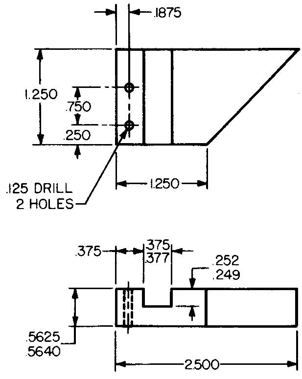
In this case, the tolerance which applies to all dimensions given in this manner is usually specified in a general note in or near the title block.
Such a note would read, "Decimal dimensions to be ±.0156 unless otherwise noted."
Specified tolerances for decimal dimensions may be shown on the drawing in any one of the three ways illustrated in Fig. 11-9.
Fig. 11-9. Methods of specifying tolerances for decimal dimensions
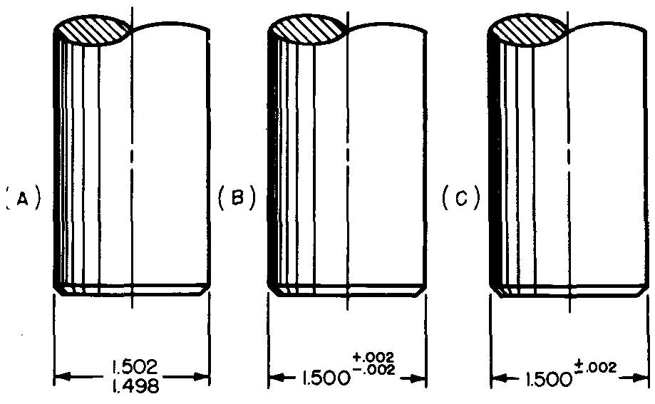
In Fig. 11-9A, the calculations have been worked out for the shopman. This preferred method reduces the errors in the shop. Figures 11-9 B and C require the shopman to calculate the limits.
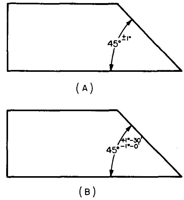
Angular tolerances
When all angular dimensions on a drawing have the same tolerance, the tolerance is specified in a general note in or near the sheet title block.
The note would read, "Angular dimensions to be ±0°-30' (or ±1/2°)."
Figure 11-10 shows two methods of specifying the tolerances for angles on a drawing.
Fig. 11-10. Methods of specifying tolerances for angular dimensions
Placing limits keys and shafts
keys and shafts
Place the largest limit over the smallest limit as shown in Figs. 11-6B and 11-7B.
The shopman starts with stock for a key or shaft which is oversize. In cutting down to size, he needs to know the largest limit first.
Slots and holes
Place the smallest limit over the largest limit as shown in Figs. 11-6B and 11-7B. In this case the shopman enlarges the slot or hole to the final size. Thus he needs to know the smallest limit first.
ASA classification of fits
The ASME (American Society of Mechanical Engineers) has developed a uniform or consistent method for applying tolerances on dimensions of machine parts.
This method is thoroughly explained in ASA B4.1-1955, Preferred Limits and Fits for Cylindrical Parts.
It defines all of the terms which are associated with fitting mating parts together and suggests standard sizes, allowances, and tolerances and various types of fits.
A table of preferred basic sizes is also included in this standard. The table contains a listing of recommended fits for parts ranging in size from 0.04 inch to 15.75 inches.
The method standardizes and defines more accurately than ever before what is meant by a loose fit, a tight fit, and so on. The method first lists five major types, or classes, of fit, ranging from a very tight fit (force fit or shrink fit) to a very loose fit (running fit or sliding fit).
In each class of fit a definite allowance is recommended. Roughly, the method can be compared to the standardization of screw threads.
That is, the ASA system essentially standardizes mating parts so that shafts which are made by one company will fit bushings of the same ASA classification of fit made by another company, in the same way that bolts manufactured by one company will fit nuts made with the same threads manufactured by another company.
Selective assembly
To help reduce the high costs of producing parts to extremely close tolerances, many companies use a process known as selective assembly.
Parts are first manufactured to loose tolerances; then, prior to assembly, they are gaged (or measured) and separated into similar size groups (usually small, medium, and large).
Small shafts, for example, are mated with small size holes, medium shafts are mated with medium size holes, and so on.
In this way, mating parts may be made to fit closely with one another, thus avoiding the necessity and added expense of working to unusually close tolerances.
Review questions (The answers are not given)
1. Explain the meaning of the term interchangeable parts.
2. Explain the meaning of the term mass production. What is perhaps the most common example of mass production?
3. Define tolerancing.
4. A shaft measures 1.6875 inch in diameter. What is the nominal size?
5. Define limits.
6. How does the machine draftsman know how much tolerance 'to use on a given part? Explain.
7. Define allowance.
8. Name the two kinds of allowance.
9. What is meant by one part interfering with another?
10. Name the allowance which always means that mating parts fit loosely together.
11. Explain what is meant by the term to apply a tolerance.
12. What is the starting point from which all calculations are made?
13. How much is the standard tolerance on a fractional dimension?
14. On a shaft with limit dimensions, why is the largest shaft size placed above the smallest?
15. How are the limit dimensions arranged for holes and slots? Explain.
16. Explain how the process of
selective assembly helps to reduce the manufacturing costs of producing parts.
Calculate the limits for the following problems.
17. Shaft and hole: nominal size of 5/8 inch; interference allowance of 0.0003 inch; tolerance on shaft is 0.0003 inch and tolerance on hole is 0.0006 inch.
18. Shaft and hole: nominal size of 1-13/16 inches; clearance allowance of 0.005 inch; tolerance on both 0.001 inch.
19. Shaft and hole: nominal size of 2-1/8 inches; interference allowance of 0.0012 inch; tolerance on shaft is 0.003 inch and tolerance on hole is 0.0015 inch.
20. Shaft and hole: nominal size of 1-3/4 inches; clearance allowance of 0.001 inch; tolerance for both is 0.0015 inch.
21. Key and slot: nominal size of 3 inches: clearance allowance of 0.0005 inch; tolerance for both 0.0015 inch.
22. Key and slot: nominal size of 1-3/8 inches; interference allowance of 0.0025 inch; tolerance for key is 0.0005 inch and tolerance for slot is 0.0010 inch.
23. Key and slot: nominal size of 5-7/8 inches; clearance allowance of 0.0015 inch; tolerance of key is 0.0010 inch and tolerance for slot is 0.0005 inch.
24. Key and slot: basic size of 1.5685 inches; interference allowance of 0.0006 inch; tolerance for key is 0.0005 inch and tolerance for slot is 0.0003 inch.
