Surface treatment of metals
Introduction
It is the responsibility of the machine draftsman to specify all information necessary for the complete manufacture of a part. He must give careful attention to the operations involved in making the part; in most cases he must also specify the desired surface treatment on the drawing.
Depending upon the requirements, the surface quality of a part may range from a rough cast to a highly polished surface.
Before the draftsman can specify the surface finish on a drawing of a part, he should know some of the basic processes commonly used to produce surface finishes.
In addition to the various ways of producing surface finishes on a part, surface treatment processes may consist of providing protective finishes on machine parts.
Specifications for surface treatments are listed in Table 6. Surface treatment specifications
This section will present an explanation of the basic elements of knurling, surface finishing, surface cleaning, and protective finishing.
Knurling
Knurling is the process of rolling depressions of various designs on unhardened cylindrical surfaces. The result is a roughening of the surface.
Hardened steel wheels, called knurls, are pressed firmly against the rotating workpiece. The knurls have ridges, or teeth, which reproduce their design on the work surface. Knurls are held in a jointed tool holder which permits the knurls to center themselves on the work, as shown in Fig. 8-1.
Fig. 8-1. a Jointed tool holder
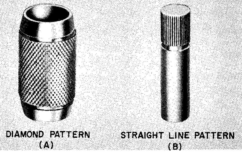
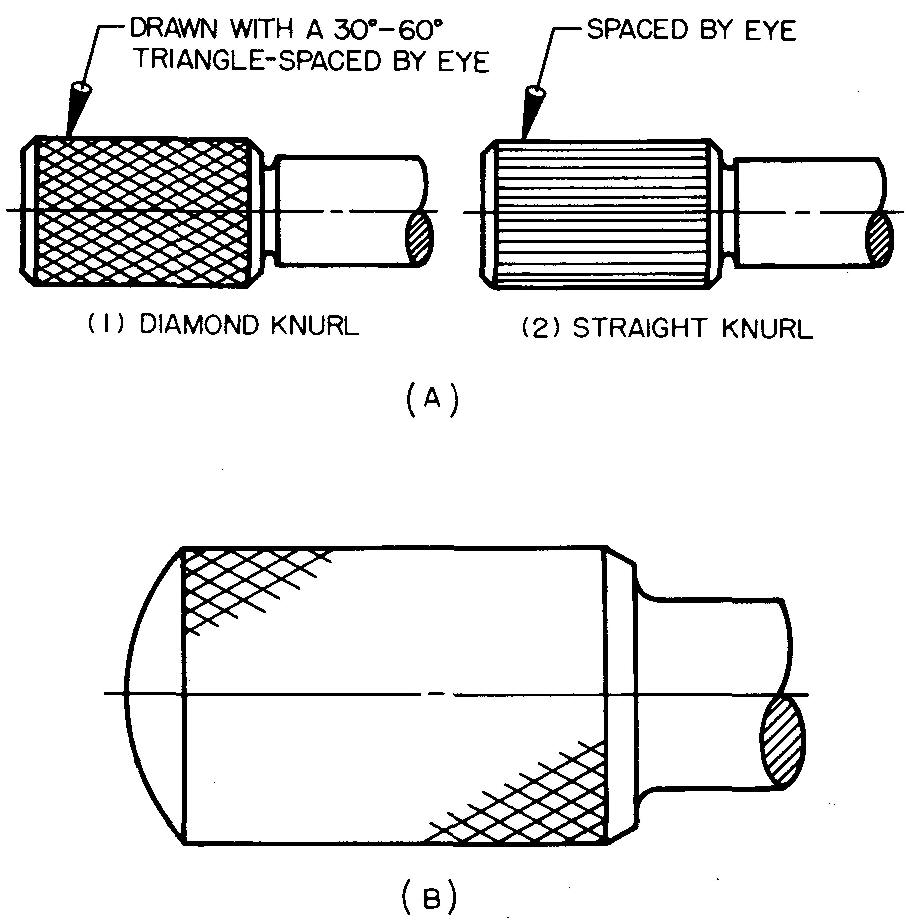
As the knurls are pressed against the work, they rotate with it. There are two kinds of knurl designs: the diamond pattern and the straight-line pattern, both shown in Fig. 8-2.
Fig. 8-2. Two kinds of knurl designs
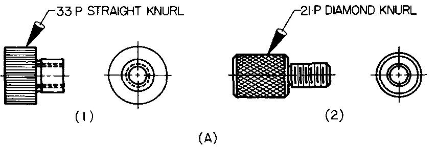
Each pattern is available as a coarse knurl (33 pitch), medium knurl (21 pitch), and fine knurl (14 pitch). Pitch refers to the number of ridges per inch. The pitch is the distance measured parallel to the axis, or center line, of the workpiece.
The pitch of a knurled surface is illustrated in Fig. 8-3.
Fig. 8-3. How pitch is measured on a knurled surface
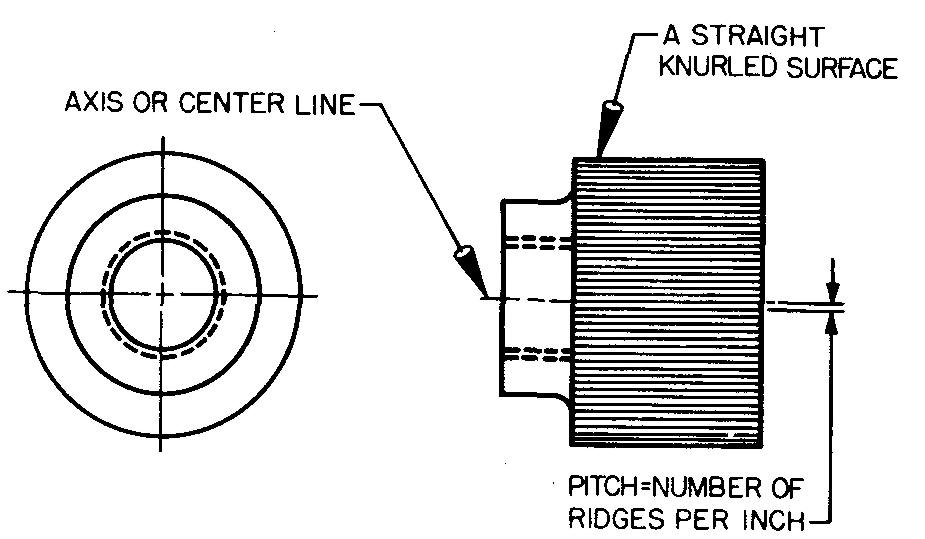
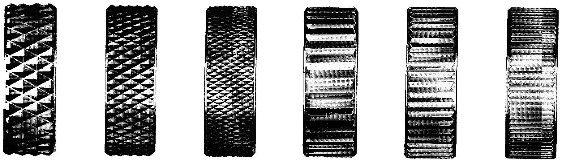
Figure 8-4 shows the actual size for each pitch in each pattern, as it has been impressed on a work surface.
Fig. 8-4. Actual size of knurl designs
The straight-line pattern is made by using only one knurl in a holder.
The diamond pattern is made by using two knurls. One knurl has teeth which incline (or slope) to the right, and the other knurl has teeth which incline to the left. As the knurls rotate, two ridges are formed, one to the left and one to the right; these cross to form a diamond shape.
Figure 8-5 shows how knurling is done on a lathe. Knurling may also be done on an automatic screw machine.
Fig. 8-5. Knurling on a lathe
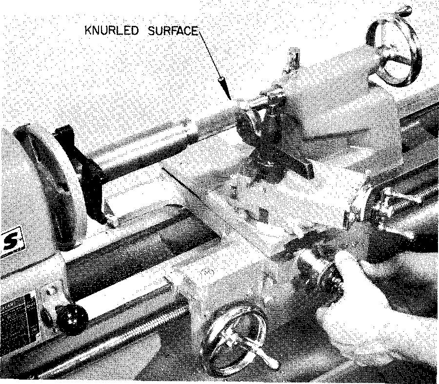
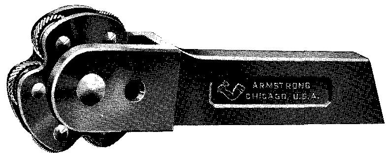
There are two reasons for knurling: to provide a gripping surface on a knob or handle, as illustrated in Fig. 8-6, and to provide a roughened surface on a shaft when a tight fit is required between the shaft and another part, as shown in Fig. 8-7.
Fig. 8-6. Gripping surface on knobs and handles of an air metallizing driven-gun known as Turbo-Jet
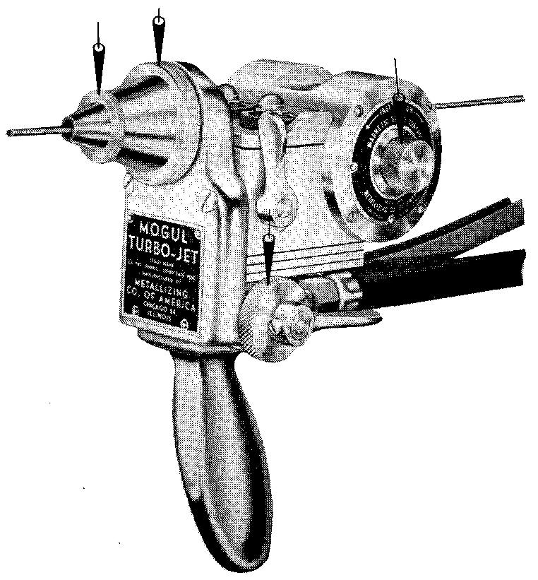
Fig. 8-7. A part knurled for a tight fit
For drawing purposes, no attempt is made to draw knurling to an accurate scale. The main requirement is to draw a knurled surface to look approximately correct. Figure 8-8 shows how knurling is represented on both small and large surfaces on machine drawings.
Fig. 8-8. Representation of knurling
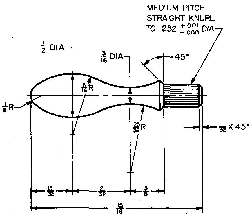
Knurling is specified on a drawing as shown in Fig. 8-9.
Fig. 8-9. Specification of knurling
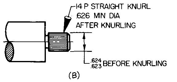
When knurling is used to provide a gripping surface, the pitch and kind of knurl should be specified. When knurling is used for the purpose of providing a tight fit between two parts, the limit dimensions before knurling and the minimum diameter after knurling must be given, as well as the pitch and the kind of knurl required.
Surface finishing
Surface finishing is a term which describes finishes produced by mechanical methods.
Methods of surface finishing
include grinding, scraping, polishing, lapping, buffing, honing, and
superfinishing. All of these methods remove varying amounts of metal from the
work surfaces on machine parts.
grinding
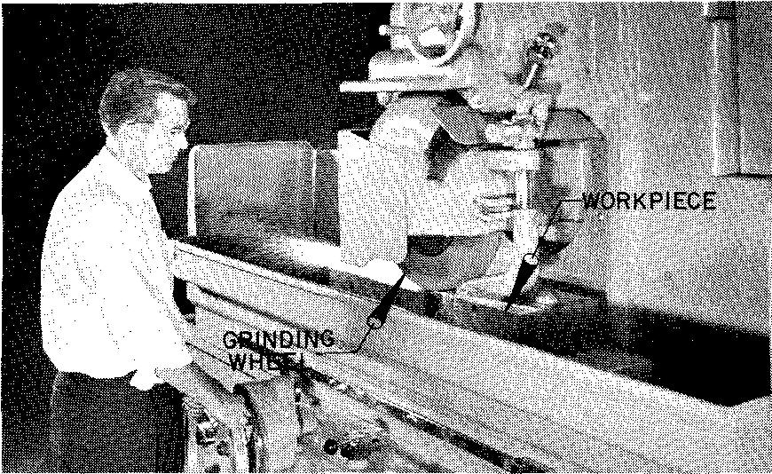
Figure 8-10 shows the process of grinding. This process consists of removing metal by means of a bonded abrasive wheel rotating at a high rate of speed in contact with the surface of the workpiece.
Fig. 8-10. a Surface grinding operation
Basically, grinding is done for the following reasons:
1. To improve or smooth the surface.
2. To finish workpieces to a precise size.
3. To remove varying amounts of stock.
4. To true surfaces of workpieces which have been warped by hardening.
5. To improve or form the cutting edge of tools such as tool bits, milling cutters, drills, and reamers.
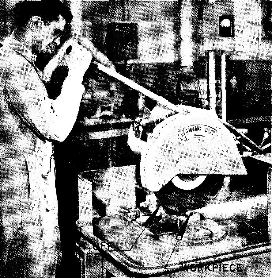
6. To cut off stock to a desired size, as shown in Fig. 8-11.
Fig. 8-11. An abrasive cut-off wheel
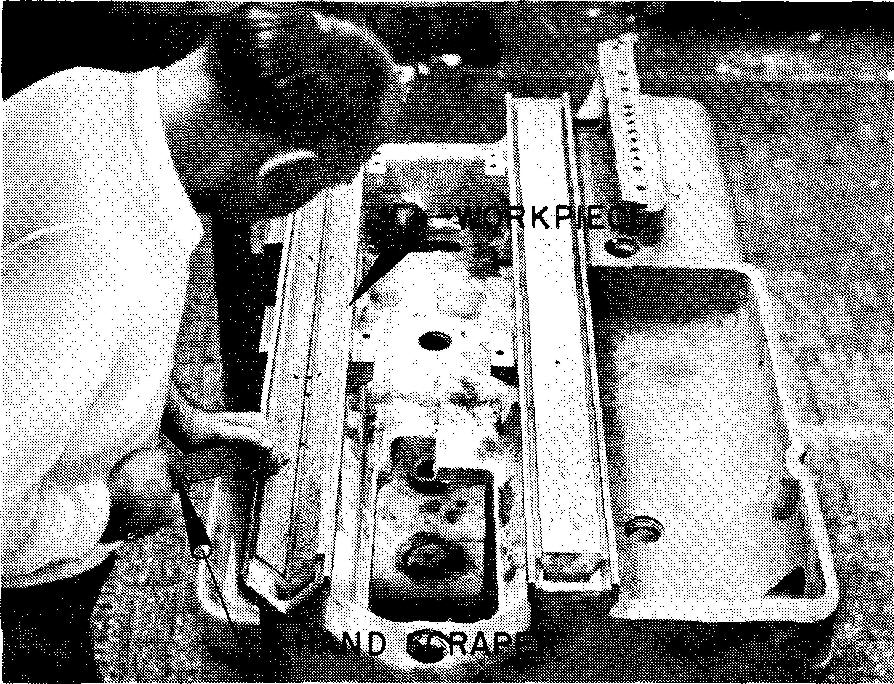
Scraping
This process consists of making a true plane, or flat surface, on a part by removing the high spots. It may be performed manually or by mechanical methods. Scraping is reserved for accurately fitting two flat parts together or for fitting together mating shafts and bearings.
Ornamental surface designs consisting of swirls in a half moon effect are produced on certain exposed surfaces of lathes, drill presses, and so on by scraping.
Scraping is done with glass-hard metal scrapers which resemble a flat file with the cutting edge at one end. Hand scraping is considered an art. It requires a long and specialized training period. A hand-scraped surface is shown in Fig. 8-12.
Fig. 8-12. A scraped surface
Polishing
Surface imperfections are removed by polishing. This process is performed by the action of abrasive particles which cling to the surface of high-speed rotating resilient (or flexible) wheels, as shown in Fig. 8-13.
Fig. 8-13. Polishing metal
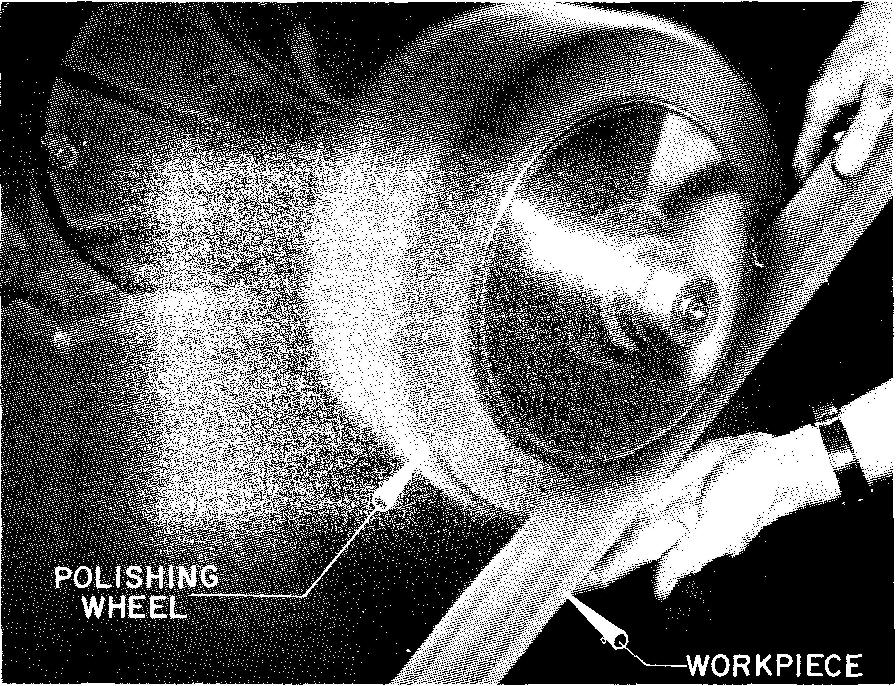
For this reason, polishing is sometimes called flexible grinding. Polishing wheels are made from wood, felt, leather, canvas, or fabric.
Forged parts and surfaces of parts which have irregular shapes, such as plow blades, axe and hammer heads, and wrenches, are usually finished by polishing. Sheet or strip stock is often polished before small parts are stamped from the stock. Stock which has a smooth surface produces less wear and tear on the stamping dies.
Also, the stamped parts usually require little additional surface finishing after they have been stamped to final shape and size.
Polishing removes the normal roughness on surfaces which is a result of the grinding or cutting operations. Steel parts are usually polished before plating.
Some parts may be finished with only one polishing operation, while other work may require several operations, starting with coarse abrasive grains and finishing with fine ones. Polishing is done on special polishing and buffing lathes.
Lapping
This process refines workpieces beyond the point of finish and accuracy produced by grinding. It is a final stock-removing operation.
Generally, not more than 0.0005 inch of stock is left for lapping. Parts are always accurately ground for size, parallelism, roundness, or flatness prior to lapping. Lapping removes surface roughness, slight distortions, tool marks, and surface fuzz left from grinding. It improves the accuracy of parts.
Lapping consists of bringing the surfaces of the workpieces in contact with a tool called a lap. Loose, fine abrasive powder, mixed with oil, grease, soap, or water, is used between the lap and the workpiece.
The work is moved in contact with the lap over an ever changing path in a continual criss-cross pattern. The general effect of lapping is to reduce the height of the high spots on surfaces of parts by means of a rubbing action. Lapping has the following advantages:
1. It provides a more uniform surface and a better finish.
2. Because of the improved flatness of the surface, it makes for a tighter seal between two parts, often eliminating the need for gaskets when liquids and gases are used. In special cases, it may eliminate the need for piston rings between a plunger and a cylinder.
3. Moving parts such as a piston and a cylinder usually must be run slowly at first for the purpose of gradually wearing down any high spots on the surfaces. Lapping these surfaces beforehand removes many of the high spots which contribute to wear on moving parts. This results in reducing the breaking-in time and in increasing the wear life of the part.
4. By removing slight errors on threaded pieces and on gears, lapping reduces noise and wear.
Lapping may be performed manually or by machine. The necessity for hand lapping is avoided whenever possible because of the difficulty in producing accurate results.
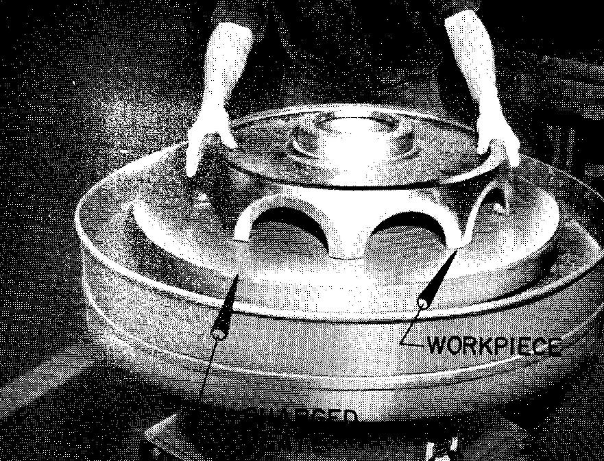
A method of machine lapping, shown in Fig. 8-14, consists of bringing the flat surfaces of the workpiece into contact with a rotating, accurately finished plate which has been charged, or coated, with a wet abrasive mixture.
Fig. 8-14. a lapping machine
Outside cylindrical surfaces are lapped by holding the work in a chuck which is mounted on a lathe. As the work rotates, the lap is brought into contact with the work surface by means of a clamp or holder.
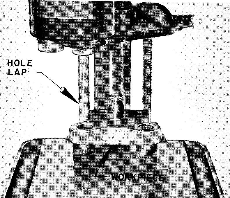
Holes are lapped in various ways according to the degree of accuracy required. Basically, a hole lap consists of a cylindrical tool which is made of wood, copper, brass, or cast iron.
The diameter of the lap is made slightly less than the hole size or so that it just enters the hole. Abrasive powder moistened with oil or water is applied to the tool prior to entry into the hole (Fig. 8-15).
Fig. 8-15. a hole lap
The process of lapping is used to refine surfaces on precision threaded parts, gears, valves, pistons, crankshafts, machine spindles, bearings, gages, and so on.
Buffing
The process of refining a surface by removing scratches and other surface imperfections is called buffing. From time to time, a fine abrasive composition is applied to a moving wheel of wool, cotton, or fabric, or to a cloth or felt belt, called a buffer. The buffer is kept in contact with the workpiece.
The abrasive composition is applied either by touching the moving buffer with a solid bar of the abrasive or by spraying it on as a liquid. Buffing produces a very fine surface. It is the method used to give a higher luster to metal surfaces both before and after plating. Parts are buffed on essentially the same machines as those used for polishing.
honing
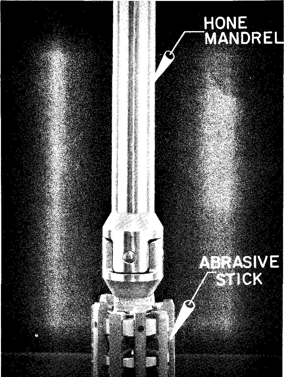
The process of removing stock from inside or outside surfaces of cylindrically shaped parts is called honing. The hone consists of a series of abrasive sticks placed lengthwise along the surface of a cylindrical metal rod called a mandrel.
A hone is shown in Fig. 8-16.
Fig. 8-16. A hone
The mandrel may be adjusted by expansion so that the sticks are held under pressure against the inner walls of the hole. The tool is rotated and moved lengthwise inside the hole. The hone can remove as much as 1/64 inch of stock. Usual shop practice is to leave from 0.001 inch to 0.002 inch of stock for honing.
Any metallic material can be honed, as well as nonmetallic materials such as glass, ceramics, and plastics. The hardness of the material does not limit the honing process; it only affects the rate at which the stock may be removed. Parts with holes ranging in size from 0.250 inch up to 42 inches in diameter may be honed.
Honing may be done manually or by mechanical methods. The machines usually used to hone parts mechanically are the drill press, the portable electric drill, and specially designed honing machines. A honing machine is shown in Fig. 8-17.
Fig. 8-17. A honing machine
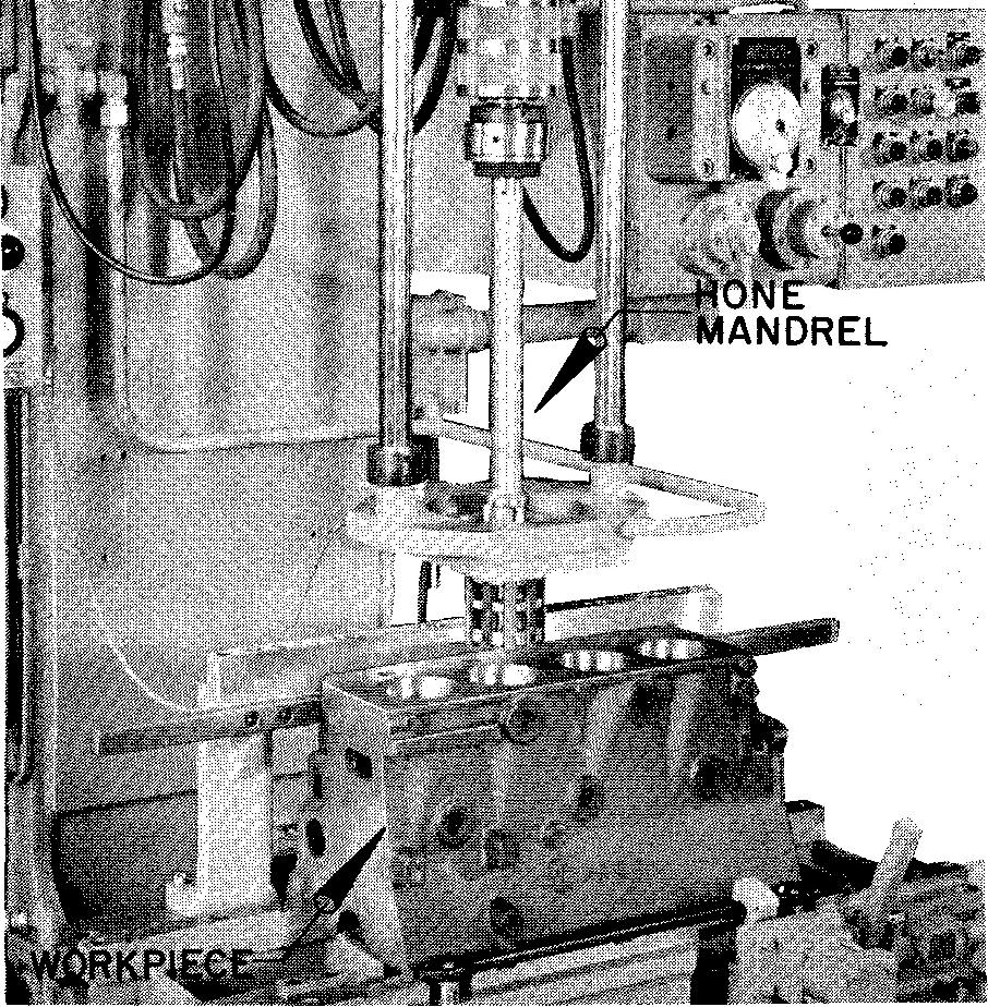
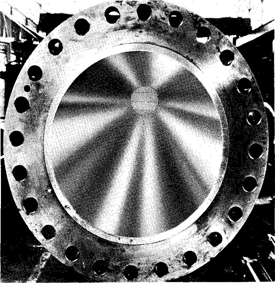
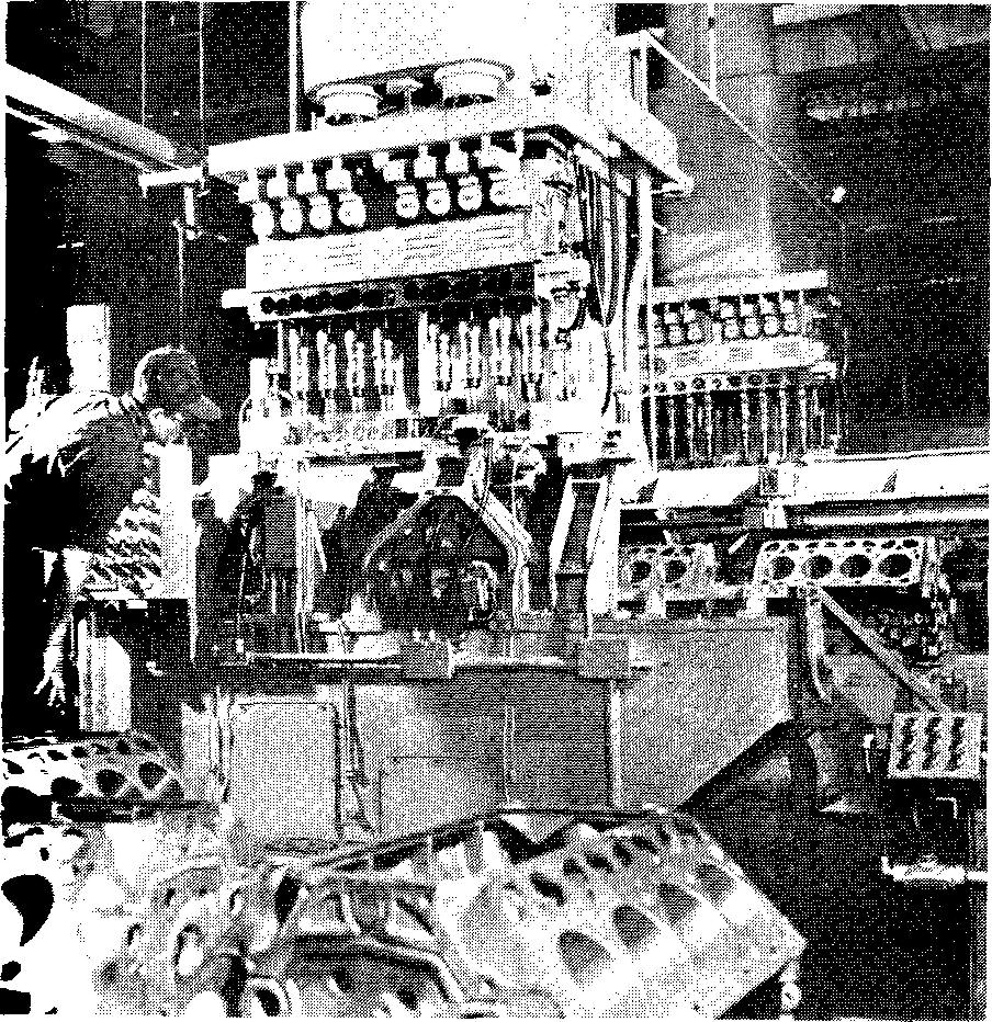
Figure 8-18 shows a long cylinder which has been honed. Figure 8-19 shows a giant honing machine.
Fig. 8-18. A 20-foot long hydraulic cylinder
The honing process is used on engine cylinders, holes for gears, gun barrels, long tubing, and so on.
Honing can produce a wide range of surface finishes. It accurately controls size. It is considered a rapid and economical method of removing stock. It can correct improper taper, out-of-roundness, and snakiness caused by previous operations. Honing can be used on both flat and round surfaces.
Fig. 8-19. A giant honing machine
Superfinishing
A method of surface finishing which was developed by David A. Wallace, formerly president of the Chrysler Division of the Chrysler Corporation, superfinishing consists of grinding by holding a fine abrasive stone against a large area of the surface of the workpiece.
The result is the production of an exceptionally smooth and wear resistant surface. The process of superfinishing is illustrated in Fig. 8-20.
Fig. 8-20. Superfinishing
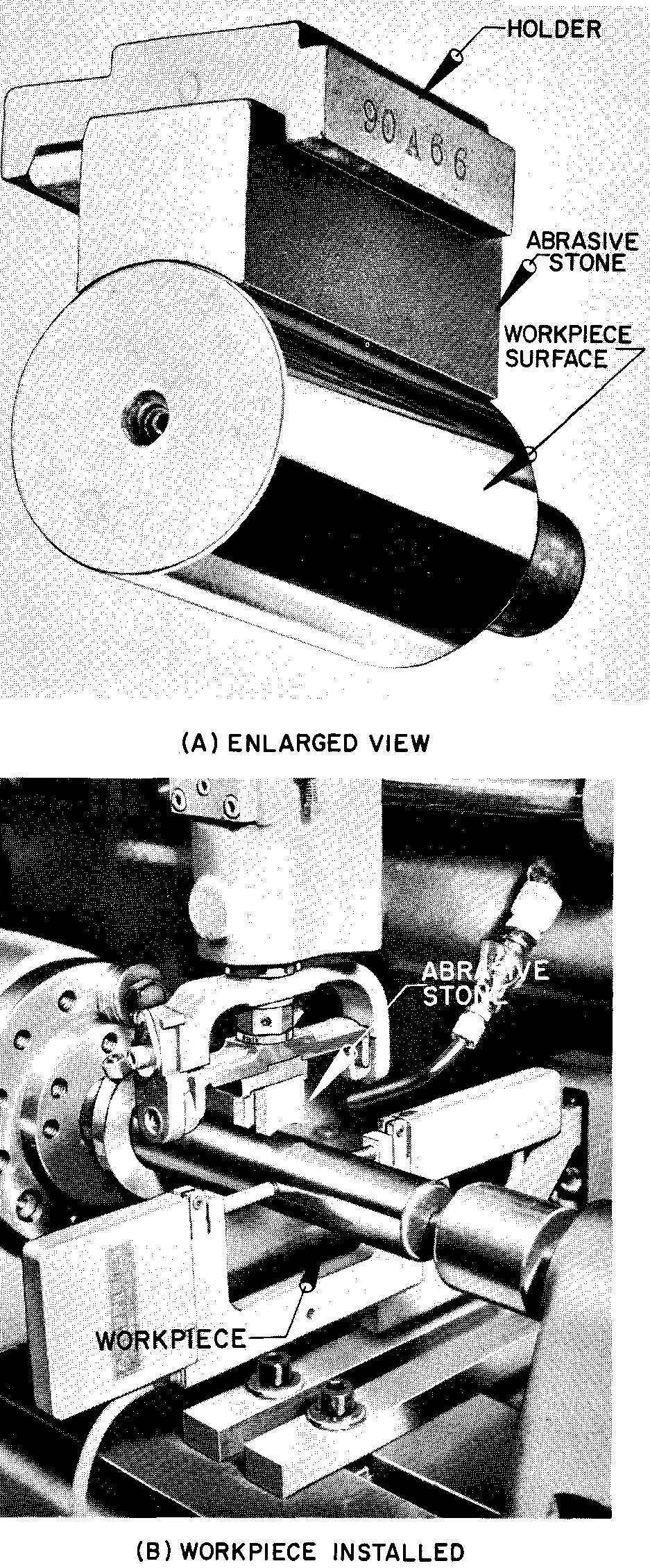
Superfinishing may be used on cylindrical, flat, spherical, or cone-shaped parts. Only a slight amount of stock is actually removed by superfinishing, usually from 0.0002 to 0.001 inch.
Superfinishing is used to produce the best surface possible. It increases the wear life on parts which are subject to wear, such as pistons, crankshafts, and bearings.
The United States Bureau of Standards has reported that the smoothness of finish has more effect on the wear of gages than the hardness of the surfaces. (A gage is a precision measuring device.)
Indicating finished surfaces
The draftsman is required to indicate on the drawing the finished surfaces of castings and forgings. (These are the surfaces which require machining after the part has been cast or forged.)
These finished surfaces are identified by certain symbols. From these symbols on the drawing the patternmaker or diemaker knows where to allow extra metal for machining.
Finish marks
Two styles of symbols are used to specify finished surfaces.
These symbols, called finish marks, are the 60° V symbol and the f symbol. The two finish marks are always used separately; one drawing never shows both symbols. However, either one or the other is used extensively on machine drawings.
Figure 8-21 illustrates both kinds of symbols and the general drawing proportions for each. For best results, the V symbol should be drawn with the 30°-60° triangle.
Fig. 8-21. Finish symbols
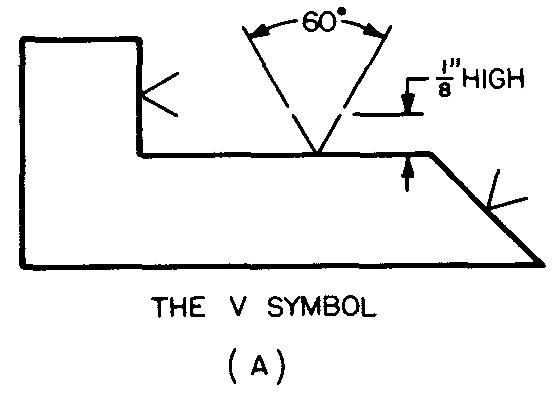
The V symbol may be drawn freehand. Note the position of the symbols on vertical, horizontal, and angular edges. The V symbol always points toward the finished edge of the part. The V symbol is tilted approximately 60° to the finished edge.
Placing finish marks
Symbols are always placed on the edge view of the required finished surface or on an extension line extending from the surface. They are shown on all views where the edge of the surface appears as either a visible or a hidden line.
Figure 14-10 (section Forming parts by casting) shows finish marks applied to both types of lines. Finish marks are omitted on holes that are made by drilling, countersinking, counterboring, and so on. They are also omitted when the machining operation is specified by note.
Finish marks are used to indicate holes which are roughly formed to shape (by casting or forging) but which will require finishing to final size, as shown in Fig. 14-10.
Finish marks are omitted on parts which are entirely formed by machining, since the manufacturing processes are obvious.
In this case, a general note is placed near the title block of the sheet. Such a note would read either FAO or Finish All Over.
Surface quality
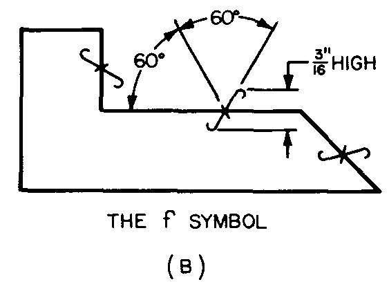
Finish marks do not indicate the quality, or degree of smoothness, of a surface. They specify only that a particular surface is to be finished. Some companies specify surface quality by using the modified method.
This is done by placing a letter in the opening of the V, as shown in Fig. 8-22. A note, or legend, is placed on the drawing explaining the numbers or letters used with the symbol.
Fig. 8-22. Modified finish symbols
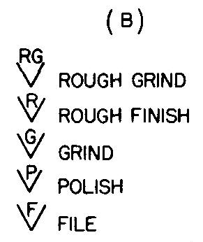
Thus, if a surface were to be rough finished, a letter R would be added to the V. If the surface were to be ground (finished by grinding) a letter G would be added. Other companies prefer a more concise method of specifying surface quality.
They use the standard listed in ASA B46.1-1955, Surface Roughness, Waviness and Lay, in which complete specifications are given. The standard specifies the degree of smoothness of surfaces. It explains the symbols which are used to control surface quality.
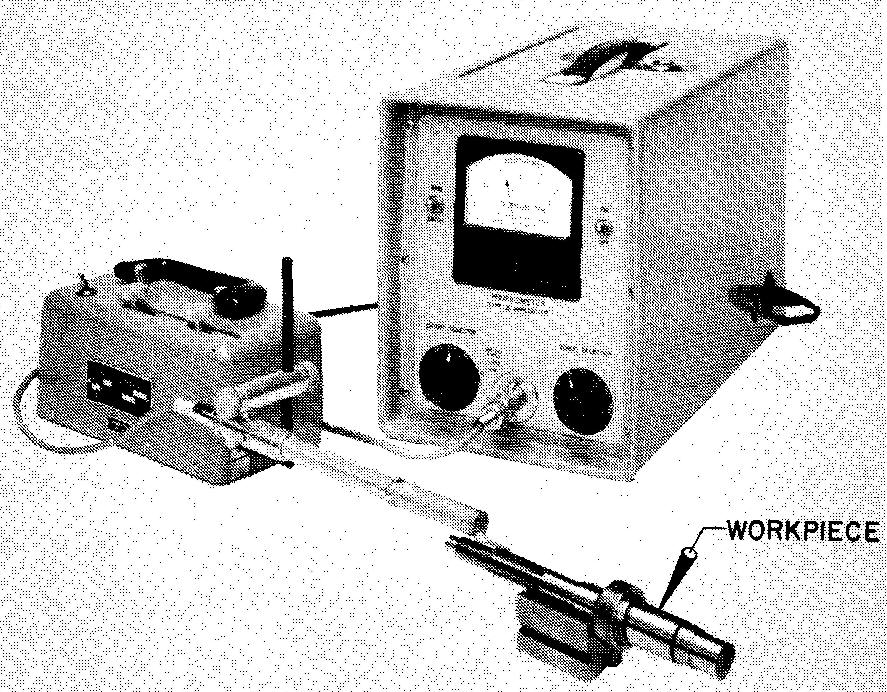
Measuring surface quality
The quality of a surface finish may be measured by using a profilometer, shown in Fig. 8-23. This instrument can measure scratches on surfaces in microinches, or millionths of an inch.
Fig. 8-23. Profilometer
Surface cleaning
Surface cleaning includes the various methods which are used to prepare or to protect final metal surfaces. Surface cleaning improves the appearance of surfaces. There are two general methods of surface cleaning: mechanical (blasting, tumbling, and power brushing) and chemical (water washing, pickling, and solvent cleaning).
Mechanical surface cleaning
Blasting
The purpose of blasting is to remove scale, rust, or other dirt particles. The process consists of directing a stream of particles against the surfaces of machine parts under moderately high pressure.
The particles consist of sand or steel, in the form of grit or shot. Blasting is generally done in a specially protected area where the particles may be prevented from flying about. The grit particles are usually collected and reused.
tumbling. This process, illustrated in Fig. 8-24, consists of inserting numerous small castings or forgings into a revolving barrel and allowing them to toss about.
Fig. 8-24. Surface cleaning by tumbling {Syntron Co.)
(A) loading the parts (B) parts after tumbling
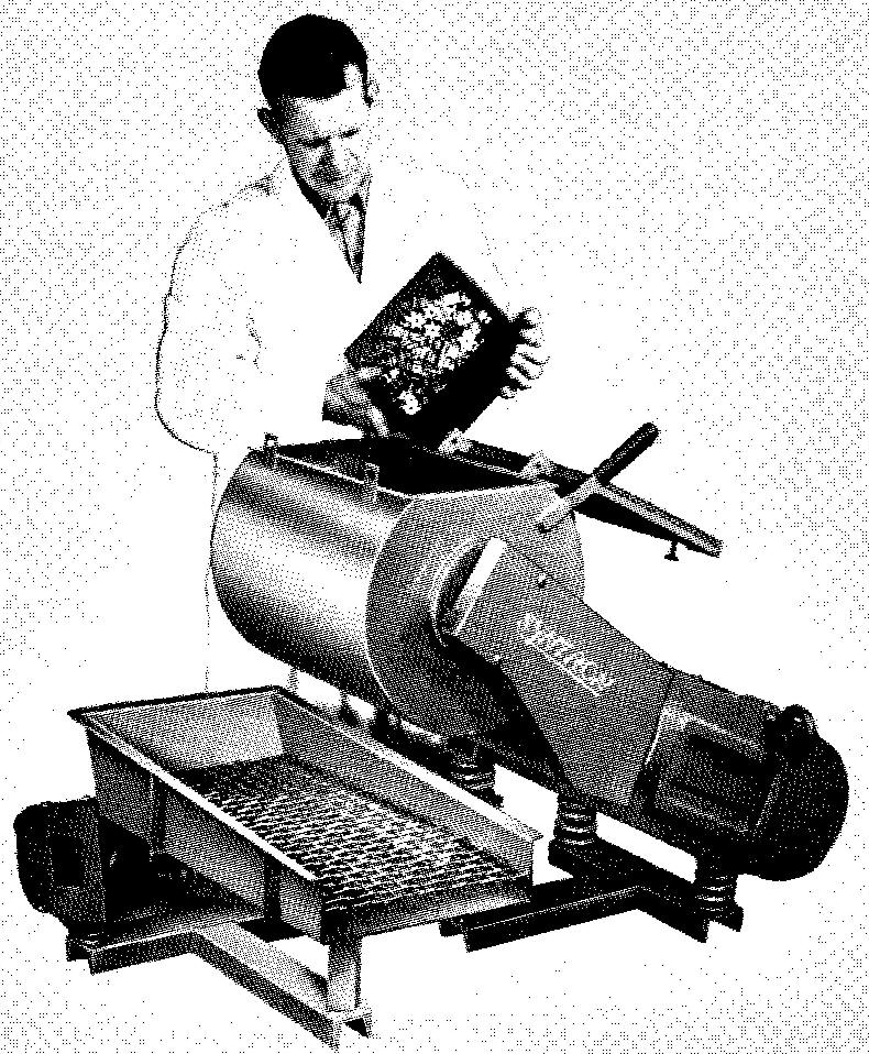
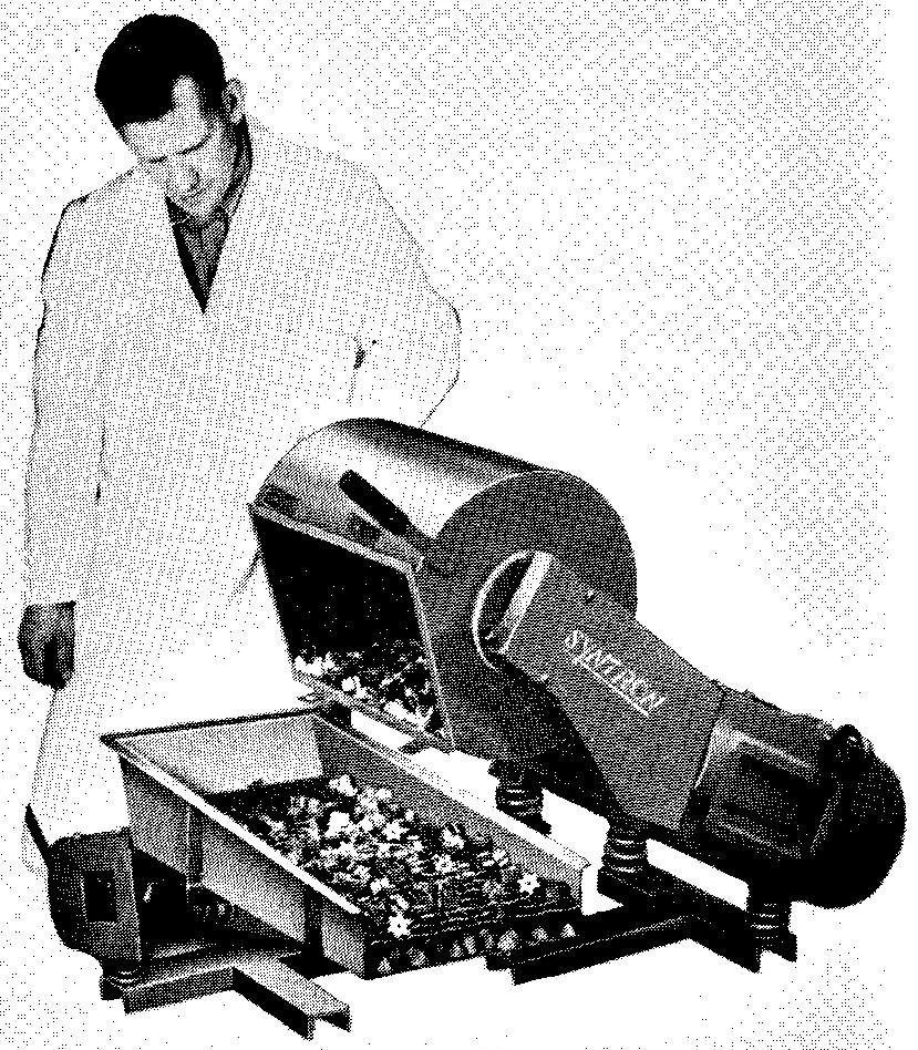
A mixture of water or oil and sand, metal chips, pumice (grinding powder), and so on is added to the barrel along with the small parts. The mixture differs according to the materials from which the parts have been made. The mixture aids in cleaning rust and scale from the parts. Tumbling is also used to remove undesirable burrs, sharp edges, fins, and corners from the parts.
Power brushing
Figure 8-25 illustrates power brushing, a process which removes burrs, scratches, and small nicks and dents by vigorously brushing the surfaces of metal parts with wire-bristle wheels.
Fig. 8-25. Surface cleaning by power brushing
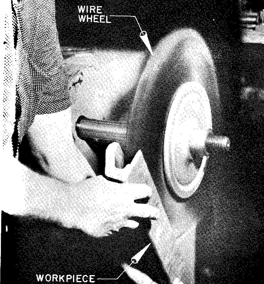
The wheels can be operated on flexible shafts, attached to bench grinders, or to polishing lathes, or to automatic polishing machines.
Chemical surface cleaning
water washing. Perhaps the cheapest and simplest way of cleaning metals, the use of water washing, depends somewhat upon the kind of impurities to be removed.
Parts are immersed into a tank of boiling water. Corrosion inhibitors (protectors) are generally added to prevent rusting. Rusting can also be prevented by drying the parts in a blast of hot air or by heating them in a drying oven.
Pickling
This process consists of cleaning parts by immersing them in a tank containing a water solution of a suitable acid. Because of their fast action and low cost, sulphuric acid and hydrochloric acid are commonly used.
Solvent cleaning
This is considered the most effective method of removing grease and oil films from metals. The parts are simply inserted into a solvent filled tank and the impurities are allowed to dissolve. There are many kinds of commercial solvents in general use.
Protective finishing
Protective finishing gives metals increased durability by building up the surfaces of the parts and by providing resistance against wear, corrosion, or weathering.
Protective finishing includes electroplating, dipping, metallizing, and various painting and coating processes.
Electroplating
The process of making electrolytic deposits of one metal on another is called electroplating.
The base metal, when covered, will have a better appearance and improved wearing qualities. Prior to plating, the metal must be thoroughly cleaned by one of the surface cleaning processes described in Sec. above.
After plating, the surfaces may be polished. Metals commonly used to plate surfaces include nickel, copper, brass, chromium, cadmium, gold, platinum, silver, tin, zinc, and lead.
The thickness of the coating varies with the metal plate and the requirements of the workpiece. Cadmium is usually plated to a thickness of 0.00015 inch to 0.0005 inch, while chromium is plated over nickel with a thickness of from 0.000015 inch to 0.00003 inch.
Dipping
The process of immersing sheets of steel or iron in baths of molten tin is known as dipping. Practically all of the steel food containers are hotdipped in this way.
Interesting to note is the fact that the common tin can is largely steel with only a 0.0003-inch to 0.0020-inch hotdipped tin coating.
Metallizing
Metallic and nonmetallic surfaces may be coated by spraying on protective layers of metal. Figure 8-26 illustrates the process of metallizing. It is similar to spray painting.
Fig. 8-26. Mogul turbo-jet metallizing gun spraying engine block valve seats
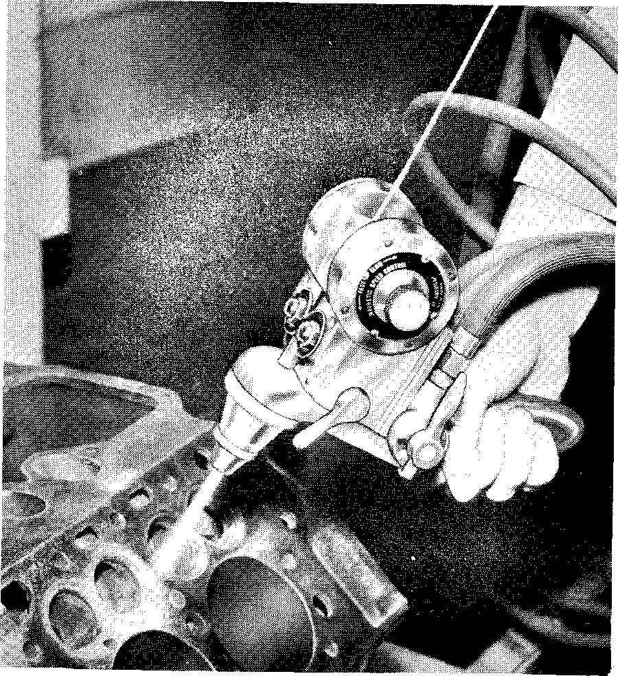
A small diameter wire from a loose coil is fed into a spray gun, where it is heated, melted into liquid droplets, and sprayed onto the work.
The droplets strike the work surface and are cooled and flattened. This process forms a coating of small interlocking plates which adhere firmly to each other.
Metallizing is used as a protective coating on storage tanks, food processing machinery, water towers, and the like. It is also used to repair worn parts which otherwise would require replacement with new parts.
For example, worn pistons, axles, camshafts, and so on have been successfully repaired by building up worn surfaces to the desired size by applying a metallic coating. Metallizing is being used more and more in the manufacture of toys and games made from nonmetallic materials.
Metals commonly used for the metallizing process include tin, aluminum, zinc, copper, brass, and bronze. The metallic coating thickness normally ranges from 1/32 inch to 1/16 inch.
Review questions (the answers are not given)
1. Surface treatment consists of what two general processes?
2. Define the process of knurling.
3. Give two reasons why parts are knurled.
4. Does the draftsman draw knurled surfaces on a part to an accurate scale? Explain.
5. Briefly describe the process of grinding.
6. Briefly describe the process of scraping.
7. List some common parts which are finished by polishing.
8. What machines are used for polishing?
9. How much stock is left on the part for lapping?
10. What operation precedes lapping?
11. Describe the process of hand lapping a flat surface.
12. Describe the tool which is used to lap holes.
13. Briefly describe the process of buffing.
14. Give several reasons why parts are honed.
15. Give one outstanding reason why some surfaces are superfinished.
16. What are the two general methods of surface cleaning?
17. What is the purpose of blasting machine parts?
18. Castings and forgings are often tumbled in a revolving barrel. What does this process do to these parts?
19. What effect does power brushing have on machine parts?
20. What method is considered to be the cheapest and simplest for cleaning metal parts? Briefly describe the process.
21. How does pickling differ from water washing?
22. What process most effectively removes grease and oil films from metal parts?
23. What is the advantage of protective finishing?
24. What are some of the metals commonly used in electroplating?
25. By what process are most of the surfaces of steel food containers protected?
26. What are the main reasons for metallizing?

![]()