Technical sketching
Experienced machine draftsmen in many drafting departments report that the ability to make rapid freehand technical sketches is almost as valuable as the ability to make mechanical drawings with instruments. In some companies, two or more detail draftsmen may often work from one centrally located assembly drawing.
Since the only available drawing must be shared, draftsmen prepare quick freehand sketches for use in making instrument drawings of the various parts. Detail draftsmen in many companies plan the views and placement of dimensions of the various parts on the drawing sheets by first making a freehand sketch.
Draftsmen are often called upon to make sketches of worn-out or broken parts on machines in the shop. Upon their return to the drafting room, the sketches are used to prepare final drawings to be used in the manufacture of new parts. Occasionally a drawing may be mislaid or lost from the engineering files.
A sketch of the actual part, which may be attached to a machine in the shop, is usually made so that a new drawing can be prepared. More and more companies today are preparing final drawings entirely by freehand methods, preferring this method, in many cases, to instrument drawings. While the practice is not widespread, it is fast gaining favor.
The views of the parts are sketched directly on the drawing sheets. A drawing number is assigned, prints are made and sent to the shop, and the sketch is placed in the engineering files for future reference.
The practice varies considerably from company to company, but, in general, sketches are usually restricted to reasonably simple parts, those produced in small quantities, and those which require only a limited number of shop operations.
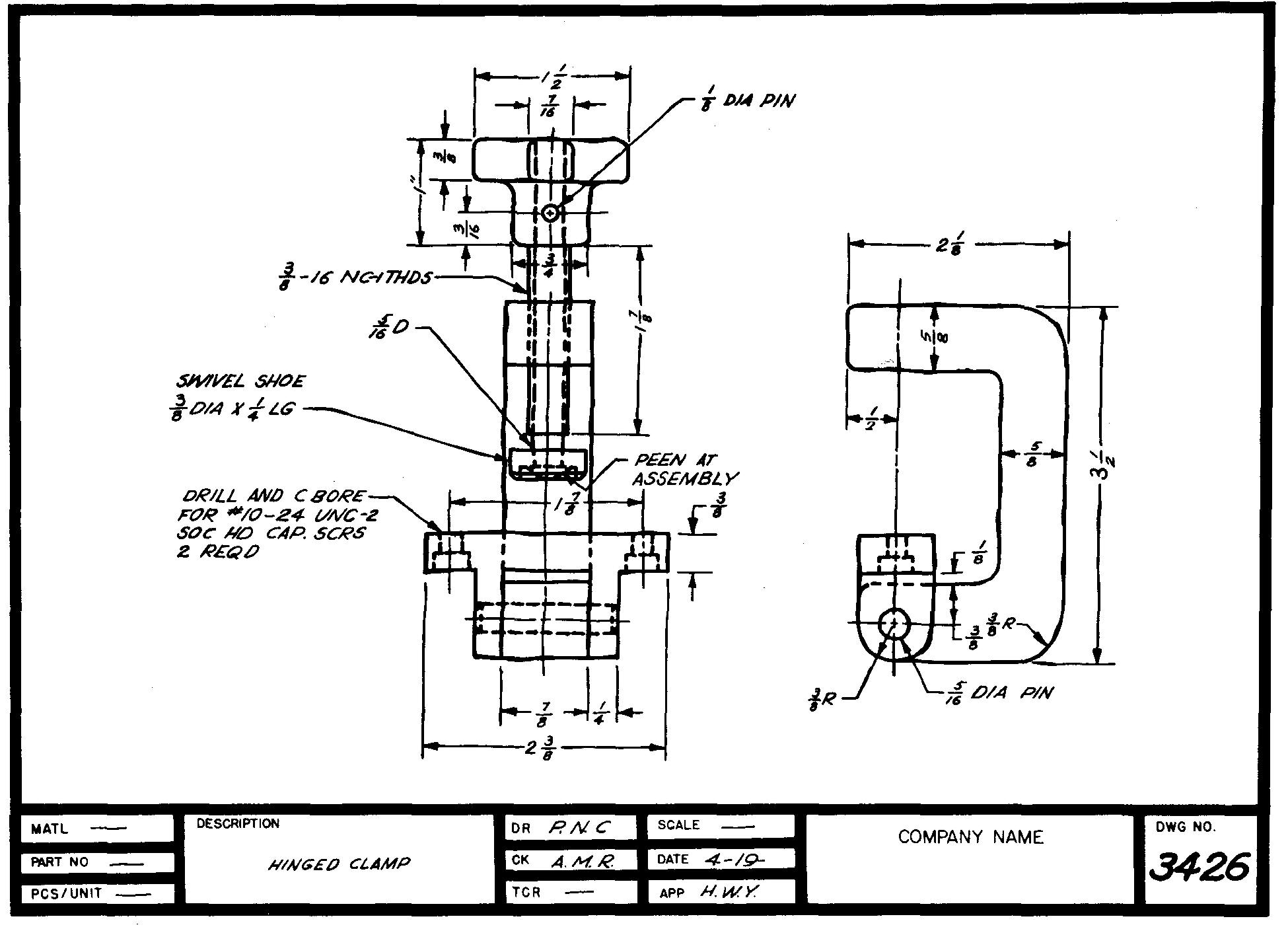
Figure 2-1 illustrates a technical working sketch which is prepared for such a part.
Fig. 2-1. A technical working sketch
Figure 2-2, a freehand pictorial sketch of a hand lever, is typical of hundreds of similar sketches which are made of parts manufactured by a leading textile machine company.
Sketches such as these are used in the shop when the sketch illustrates only a few shop operations. Such sketches are particularly useful for parts made by casting and forging. The ability to make a rapid freehand sketch is also especially valuable in setting up a mathematics problem.
Such problems usually consist of working out distances, represented by dimensions on the drawing, from one element of a part to another.
Sketches have proven especially helpful to engineers, designers, and draftsmen, who start many problems by preparing a picture showing both the known and the unknown information.
Quality of sketches
The quality of the sketch depends upon its intended use.
A rough and incomplete sketch is suitable for the draftsman who makes a hurried visit to the shop for the purpose of determining just a few sizes on a particular part.
A rough sketch is particularly suitable in the case of the draftsman who uses his own sketch as an aid in preparing final instrument drawings.
On the other hand, a sketch which may be used in the shop and later stored in the files as a permanent record would necessarily be made more carefully.
Many students, when receiving beginning instructions in technical sketching, have admitted to the author, "I cannot draw a straight line.
I have never been able to make a good sketch." After close attention to a series of simple, practical steps for developing the technique of sketching, most students eventually acquire abilities far beyond their initial expectations.
After some practice, most students are soon capable of producing sketches of extremely good quality.
Sketching materials
Successful illustrators have found the soft leads, H, HB, and F, with the point slightly dulled, to be best for sketching. The only other materials required are a suitable eraser and a sheet of paper.
The paper may be plain (or unruled). Some people prefer to use cross section paper which is ruled off with fine lines forming 1-inch squares which are further divided into 1/10, 1/8, or 1/4 inch squares.
Cross section paper is especially useful for estimating proportions of the various features of a part. Its use helps the draftsman to produce straight lines or square corners in the sketch.
Holding the pencil
For best results, the pencil should be held naturally but at a greater distance from the point than when used for writing.
Holding the pencil in this manner permits more freedom of movement of the pencil point. It also enables the draftsman to see, without interference of his hand or fingers, the immediate area around the lines he is producing on the paper.
Scale and proportion
Sketches are not made to an accurate scale. An object may be sketched to a close approximation of the actual size or it may be reduced or enlarged.
Regardless of the size of the sketch, the relationship between the main proportions (length, height, and depth) of the object and of the various slots, holes, and cuts must be carefully considered.
For example, the sketch of the part shown in Fig. 2-3 indicates how the proportions are estimated.
Fig. 2-3. Estimating proportions
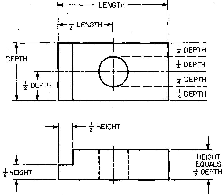
Comparisons of sizes for sketches are made entirely by eye. Draftsmen use one dimension of the part as a reference measure. The other sizes are compared to this.
Sketching straight lines
Short lines
Use short, definite strokes with a free and easy finger motion for short lines. Avoid pressing the pencil point down heavily on the paper. Sketch the lines from left to right, generally in a direction away from the body. Start by sketching a light practice line and then darken in to produce the final line as shown in Fig. 2-4.
Fig. 2-4. Sketching short lines
Long lines
A free and easy arm motion is recommended for sketching long lines. Think of swinging the pencil point through a series of long, overlapping strokes by pivoting about the muscle of the forearm.
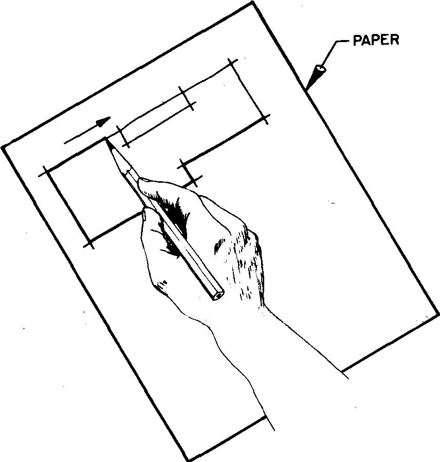
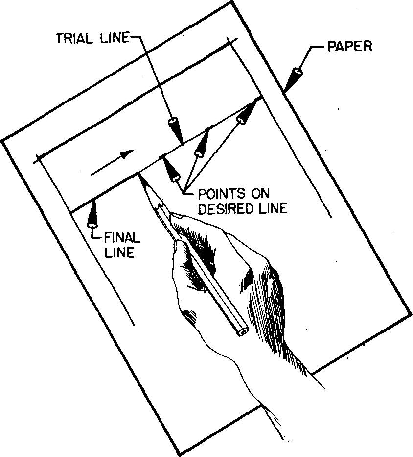
Long lines, like shorter ones, are sketched from left to right. When one is sketching lines which extend entirely or nearly across the paper, good results may be obtained by marking the end points and a few other points along the desired line with small dots.
Draw a light trial line connecting the dots with a few trial sweeps of the pencil. The eye should concentrate on the forward dot, or toward the direction of the pencil stroke.
After a suitably light line has been sketched, the line may be darkened, or heavied in, as shown in Fig. 2-5.
Fig. 2-5. Sketching long lines
Horizontal, vertical, and inclined lines
Horizontal and vertical lines should always be parallel to the edges of the paper.
When such lines are being sketched, it is helpful to divide one's attention between the link be ing sketched and the nearest edge of the paper. This should result in a correctly spaced line which is approximately the same distance away from the edge of the paper at all points.
Sketching vertical and inclined lines by pulling the pencil point down the paper toward the body usually produces an irregular or wavy result. The movement is awkward and uncomfortable. It limits the free and easy motions necessary for making good lines.
Many illustrators have found it helpful to turn the paper or sketching pad to a convenient angle for all lines, regardless of whether the intended line is to be horizontal, vertical, or inclined. Thus, all lines may be sketched by using the same movements.
Angles
The angles in a sketch are also estimated. It is possible to draw angles which are close to the desired size.
To begin sketching an estimated angle, start with the intersection of a vertical and a horizontal line. This intersection forms a 90° angle, as shown in the upper left corner of Fig. 2-6A.
Fig. 2-6. Sketching angles
The desired angles may be developed from this 90° angle. Figure 2-6B shows an approximate angle of 45°.
To draw this, estimate and mark off OX equal to OY.
Draw line XY.
Draw line OZ, which forms two approximately equal angles of about 45°.
Similar methods for the construction of angles of 30° and 15° are shown in Fig. 2-6C and D.
Circles and arcs
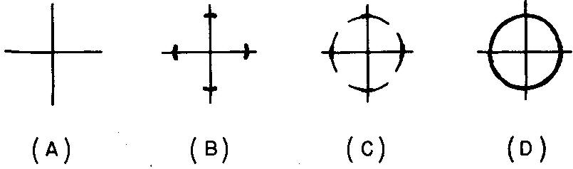
Small circles (less than 3/8- to 1/2-inch diameter) may be conveniently sketched by constructing horizontal and vertical lines which intersect at the center of the desired circle, as shown in Fig. 2-7A.
Radial distances are then marked off by eye as shown in Fig. 2-7B.
Finally, short arcs are sketched through the points (Fig. 2-7C) and the circle is completed by heavying in as shown in Fig. 2-7D.
Fig. 2-7. Sketching small circles
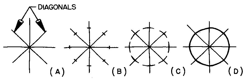
Larger circles are best sketched by using two additional construction lines (called diagonals), as shown in Fig. 2-8A. The final circle is obtained by a method similar to Fig. 2-7, except that eight points are used as shown in Fig. 2-8 B through D.
Fig. 2-8. Sketching large circles
Another method which may be used to sketch large circles is to construct a square with each side equal to the diameter of the desired circle, as shown in Fig. 2-9A.
Estimate the midpoint of the sides (Fig. 2-9B) and sketch short tangent arcs as shown in Fig. 2-9C.
Fig. 2-9. Sketching large circles
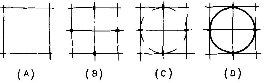
Complete the circle by heavying in as shown in Fig. 2-9D.
Diagonals may also be used in this construction as an aid in sketching the circle to an even greater degree of accuracy.
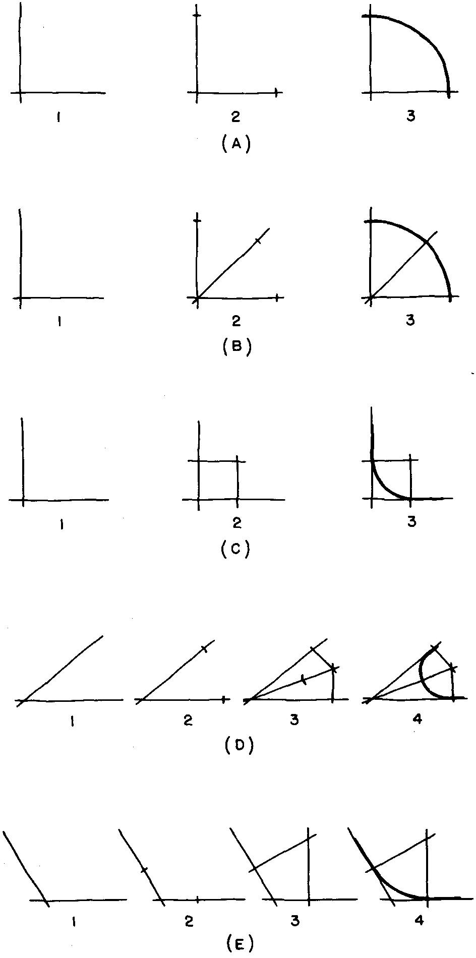
The methods for sketching arcs are similar to those explained for circles. Figure 2-10 illustrates several convenient methods.
Fig. 2-10. Sketching arcs
Blocking in the views
Most successful sketches are started by studying the object closely to determine the views which best describe the shape of the object.
Next, the size of the available space on the paper is determined. Light horizontal construction lines of sufficient length are then sketched to block in the outline of the views.
The paper is then turned to a convenient position to allow the draftsman to sketch the vertical lines with the same arm movement used for the horizontal lines. Blocking in the views helps to obtain the general proportions and also aids in balancing the sketch on the paper.
The final features of the part may now be similarly constructed within the blocked-in outline of the views. Figure 2-11 shows the necessary steps for blocking in the views and completing the sketch of a machine part.
Fig. 2-11. Steps in sketching a machine part
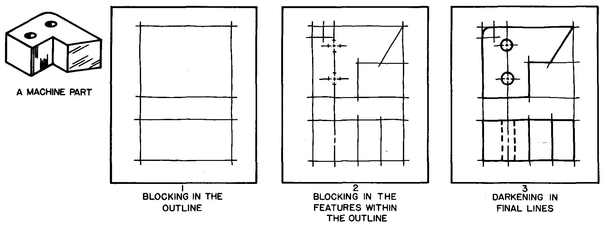
Compare the light line weights used to block in the views to the heavy lines used to sketch the final outline of the subject.
Layout lines may be erased after the final object lines are drawn. If layout lines are very light they may be left on the final sketch.
Problems for this sectiom technical sketching will be found at the end of section Principles of detail drawings. The student should not attempt these problems until he has studied the contents of this section.

![]()