
American National Standard Running and Sliding Fits ANSI B4.1-1967 (R2004)
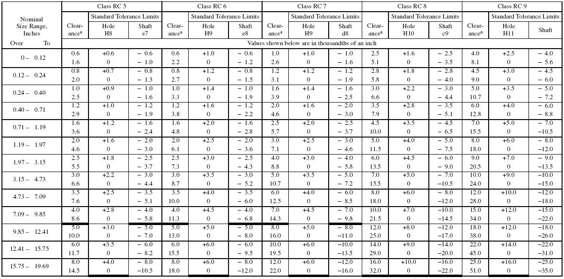
a Pairs of values shown represent minimum and maximum amounts of clearance
resulting from application of standard tolerance limits. Tolerance limits given
in body of table are added to or subtracted from basic size (as indicated by +
or − sign) to obtain maximum and minimum sizes of mating parts.
All data above heavy lines are in accord with ABC agreements. Symbols H5, g4,
etc. are hole and shaft designations in ABC system. Limits for sizes above 19.69
inches are also given in the ANSI Standard.
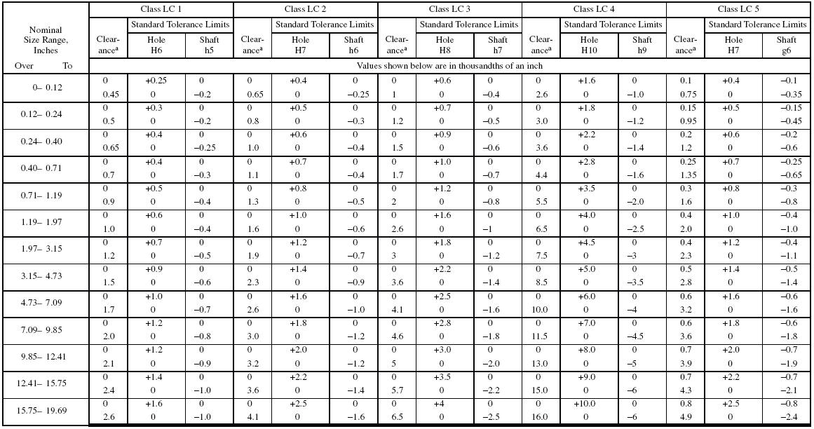
Tolerance limits given in body of table are added or subtracted to basic size
(as indicated by + or − sign) to obtain maximum and minimum sizes of mating
parts. All data above heavy lines are in accordance with
American-British-Canadian (ABC) agreements. Symbols H6, H7, s6, etc. are hole
and shaft designations in ABC system.
Limits for sizes above 19.69 inches are not covered by ABC agreements but are
given in the ANSI Standard.

a Pairs of values shown represent minimum and maximum amounts of interference
resulting from application of standard tolerance limits.

a Pairs of values shown represent maximum amount of interference (−) and maximum
amount of clearance (+) resulting from application of standard tolerance limits.
All data above heavy lines are in accord with ABC agreements. Symbols H7, js6, etc., are hole and shaft designations in the ABC system.

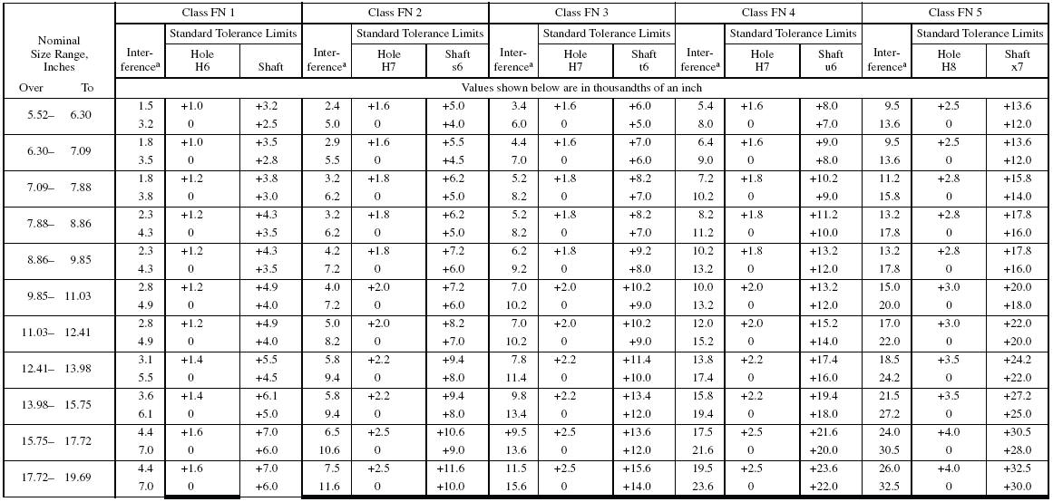
a Pairs of values shown represent minimum and maximum amounts of interference
resulting from application of standard tolerance limits.
All data above heavy lines are in accordance with American-British-Canadian (ABC) agreements. Symbols H6, H7, s6, etc., are hole and shaft designations in the ABC system. Limits for sizes above 19.69 inches are not covered by ABC agreements but are given in the ANSI standard.

All data in this table are in accordance with American-British-Canadian (ABC)
agreements.
Limits for sizes above 19.69 inches are not covered by ABC agreements but are
given in the ANSI
Standard.
Symbols H7, p6, etc., are hole and shaft designations in the ABC system.
Tolerance limits given in body of table are added or subtracted to basic size
(as indicated by + or −
sign) to obtain maximum and minimum sizes of mating parts.S

![]()