Agc circuit using a single transistor BA546, LM324
Amplifiers / Operational amplifier
In this project, you are going to learn how automatic gain control (AGC) works by hearing of a 1-kHz tone varies. When there is no input signal from the microphone, the 1 -kHz tone is heard from the speaker. When an input signal comes from the microphone, the level of the tone is reduced in accordance with the level of the microphone input, so the tone from the speaker becomes smaller.
When you finish wiring, turn power ON. In the first place, make sure you hear a 1-kHz tone from the speaker without speaking to the earphone. Turn the control volume to adjust for a rather loud tone. Then, direct your voice, or other sound, to the earphone. What happened?
Did you hear the 1-kHz tone?
The AGC circuit has determined the loudness of your voice and attenuated the 1 -kHz tone. Try to check the workings of the AGC by changing the loudness of your voice to the earphone.
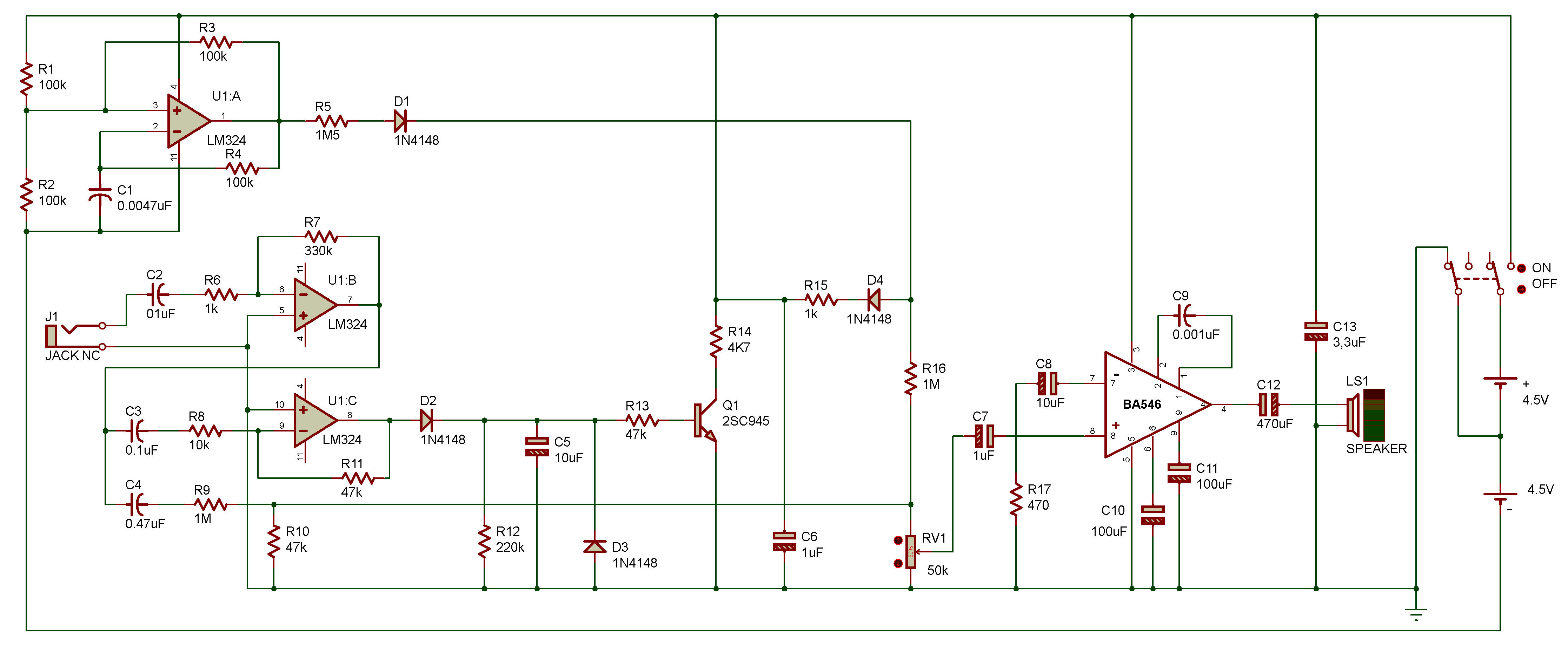
U1A is an oscillating circuit for producing a square wave of approx. 1 kHz, and U1B is an OP amplifier that amplifies the earphone input.
The inputs from these sources get mixed with the control volume, and then pass through the speaker drive amplifier BA546 before they are put out of the speaker.
U1C further amplifies the earphone input from U1B, and the output from U1C is peak-held by D2 and C5. The peak-held level is applied to the AGC circuit consisting of Q1, which attenuates the 1 -kHz tone.

![]()